Asus P5AD2-E Premium User Guide - Page 61
Starting up for the first time
 |
View all Asus P5AD2-E Premium manuals
Add to My Manuals
Save this manual to your list of manuals |
Page 61 highlights
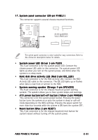
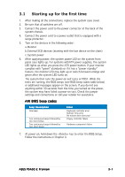
3.1 Starting up for the first time 1. After making all the connections, replace the system case cover. 2. Be sure that all switches are off. 3. Connect the power cord to the power connector at the back of the system chassis. 4. Connect the power cord to a power outlet that is equipped with a surge protector. 5. Turn on the devices in the following order: a. Monitor b. External SCSI devices (starting with the last device on the chain) c. System power 6. After applying power, the system power LED on the system front panel case lights up. For systems withATX power supplies, the system LED lights up when you press the ATX power button. If your monitor complies with "green" standards or if it has a "power standby" feature, the monitor LED may light up or switch between orange and green after the system LED turns on. The system then runs the power-on self tests or POST. While the tests are running, the BIOS beeps (see BIOS beep codes table below) or additional messages appear on the screen. If you do not see anything within 30 seconds from the time you turned on the power, the system may have failed a power-on test. Check the jumper settings and connections or call your retailer for assistance. AMI BIOS beep codes Beep Description One beep Two continuous beeps followed by two short beeps Two continuous beeps followed by four short beeps Error Keyboard controller error Refresh Time error No master drive detected Floppy controller failure Hardware component failure 7. At power on, hold down the key to enter the BIOS Setup. Follow the instructions in Chapter 4. ASUS P5AD2-E Premium 3-1
-
 1
1 -
2
-
3
-
4
-
5
-
6
-
7
-
8
-
9
-
10
-
11
-
12
-
13
-
14
-
15
-
16
-
17
-
18
-
19
-
20
-
21
-
22
-
23
-
24
-
25
-
26
-
27
-
28
-
29
-
30
-
31
-
32
-
33
-
34
-
35
-
36
-
37
-
38
-
39
-
40
-
41
-
42
-
43
-
44
-
45
-
46
-
47
-
48
-
49
-
50
-
51
-
52
-
53
-
54
-
55
-
 56
56 -
 57
57 -
 58
58 -
 59
59 -
 60
60 -
 61
61 -
 62
62 -
 63
63 -
 64
64 -
 65
65 -
 66
66 -
67
-
68
-
69
-
70
-
71
-
72
-
73
-
74
-
75
-
76
-
77
-
78
-
79
-
80
-
81
-
82
-
83
-
84
-
85
-
86
-
87
-
88
-
89
-
90
-
91
-
92
-
93
-
94
-
95
-
96
-
97
-
98
-
99
-
100
-
101
-
102
-
103
-
104
-
105
-
106
-
107
-
108
-
109
-
110
-
111
-
112
-
113
-
114
-
115
-
116
-
117
-
118
-
119
-
120
-
121
-
122
-
123
-
124
-
125
-
126
-
127
-
128
-
129
-
130
-
131
-
132
-
133
-
134
-
135
-
136
-
137
-
138
-
139
-
140
-
141
-
142
-
143
-
144
-
145
-
146
-
147
-
148
-
149
-
150
-
151
-
152
-
153
-
154
-
155
-
156
-
157
-
158
-
159
-
160
-
161
-
162
-
163
-
164
-
165
-
166
 |
 |