Brother International BAS-375E Programmer Instruction Manual - English - Page 206
Table of extended option output, Extended option, Common output condition *1, Connector *2, output No.
 |
View all Brother International BAS-375E manuals
Add to My Manuals
Save this manual to your list of manuals |
Page 206 highlights
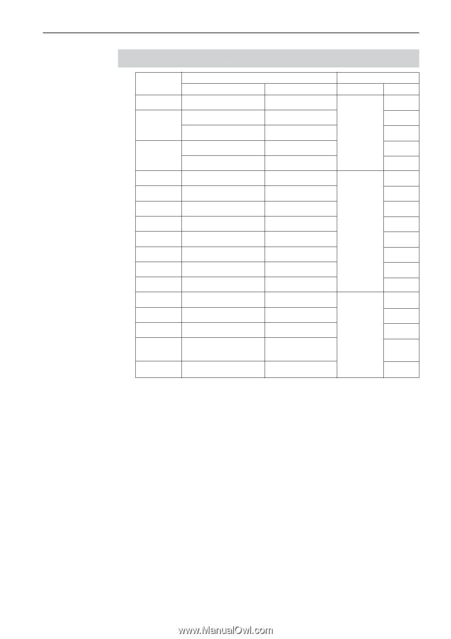
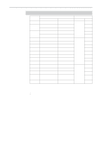
Chapter 4 Extended Option Output Table of extended option output Extended option output No. Common output (condition) *1 Part name Condition 1 2 stage tension Memory SW-0b ON Connector *2 Connector No. Pin No. 5 2 Air wiper Memory SW-09 ON 6 Pattern engraving drill Memory SW-10 ON P4(AIR) 6 3 Auto eject Memory SW-03 ON 7 Upper/lower engraving Memory SW-10 ON 7 4 Right work clamp turnover Memory SW-19 ON 1 5 Left work clamp turnover Memory SW-19 ON 2 6 3 7 P21(EXOUT) 4 8 5 9 Signal tower green Memory SW-15 ON 6 10 Signal tower yellow Memory SW-15 ON 7 11 Signal tower red Memory SW-15 ON 8 12 NEEDLE DIPSWB-4 ON 8 13 FLIP DIPSWA-6 ON 4 14 FOOT DIPSWC-6 ON P4(AIR) 3 15 LCLAMP When 2 stage pressure 2 bar is used 16 RCLAMP For the air type 1 *1 Input available for optional parts. It is not used as extended option input if conditions are met. *2 Connector number and pin number on the main circuit board in the control box ɾThe common terminal of connector P4 (AIR) is pin No. 11 at +24V. ɾThe common terminal of connector P21 (EXOUT) is pin No. 9 or 10 at +24V. Programmer 205
-
 1
1 -
2
-
3
-
4
-
5
-
6
-
7
-
8
-
9
-
10
-
11
-
12
-
13
-
14
-
15
-
16
-
17
-
18
-
19
-
20
-
21
-
22
-
23
-
24
-
25
-
26
-
27
-
28
-
29
-
30
-
31
-
32
-
33
-
34
-
35
-
36
-
37
-
38
-
39
-
40
-
41
-
42
-
43
-
44
-
45
-
46
-
47
-
48
-
49
-
50
-
51
-
52
-
53
-
54
-
55
-
56
-
57
-
58
-
59
-
60
-
61
-
62
-
63
-
64
-
65
-
66
-
67
-
68
-
69
-
70
-
71
-
72
-
73
-
74
-
75
-
76
-
77
-
78
-
79
-
80
-
81
-
82
-
83
-
84
-
85
-
86
-
87
-
88
-
89
-
90
-
91
-
92
-
93
-
94
-
95
-
96
-
97
-
98
-
99
-
100
-
101
-
102
-
103
-
104
-
105
-
106
-
107
-
108
-
109
-
110
-
111
-
112
-
113
-
114
-
115
-
116
-
117
-
118
-
119
-
120
-
121
-
122
-
123
-
124
-
125
-
126
-
127
-
128
-
129
-
130
-
131
-
132
-
133
-
134
-
135
-
136
-
137
-
138
-
139
-
140
-
141
-
142
-
143
-
144
-
145
-
146
-
147
-
148
-
149
-
150
-
151
-
152
-
153
-
154
-
155
-
156
-
157
-
158
-
159
-
160
-
161
-
162
-
163
-
164
-
165
-
166
-
167
-
168
-
169
-
170
-
171
-
172
-
173
-
174
-
175
-
176
-
177
-
178
-
179
-
180
-
181
-
182
-
183
-
184
-
185
-
186
-
187
-
188
-
189
-
190
-
191
-
192
-
193
-
194
-
195
-
196
-
197
-
198
-
199
-
200
-
 201
201 -
 202
202 -
 203
203 -
 204
204 -
 205
205 -
 206
206 -
 207
207 -
 208
208 -
 209
209 -
 210
210 -
 211
211 -
212
-
213
-
214
-
215
-
216
-
217
-
218
-
219
-
220
-
221
-
222
-
223
-
224
-
225
-
226
 |
 |