Canon BJC 6000 Service Manual
Canon BJC 6000 - Color Inkjet Printer Manual
 |
View all Canon BJC 6000 manuals
Add to My Manuals
Save this manual to your list of manuals |
Canon BJC 6000 manual content summary:
- Canon BJC 6000 | Service Manual - Page 1
REVISION 0 JAN. 1999 QY8-1361-000 COPYRIGHT © 1999 CANON INC. CANON BJC-6000 SE 0199 0.30-0 PRINTED IN JAPAN (IMPRIME AU JAPON) - Canon BJC 6000 | Service Manual - Page 2
0199 SE 0.30-0 - Canon BJC 6000 | Service Manual - Page 3
- Canon BJC 6000 | Service Manual - Page 4
This manual was produced on an Apple Macintosh™ Power Mac 9600/233 personal computer and Apple LaserWriter™ II NTX-J laser beam printer; final pages were printed on Varityper™ 5300 with 4000-J RIP. A Canon mo-5001S Magneto-Optical Storage Subsystem with mo-502M Magneto-Optical Storage Disk Cartridge - Canon BJC 6000 | Service Manual - Page 5
for servicing the BJC-6000 printer. Part 1: Safety and Precautions This part contains information on how to service the unit safety. It is very important, and must be read. Part 2: Product Specifications This part outlines the product and its specifications. Part 3: Operating Instructions This part - Canon BJC 6000 | Service Manual - Page 6
1.5 Consumables 1.5.1 Black, color, and photo BJ cartridges 1.5.2 Ink tanks 2. SPECIFICATIONS 2.1 General Specifications 2.2 Paper Specifications 2.3 Interface Specifications Part 3: OPERATING INSTRUCTIONS 1. PRINTER SETUP 1.1 Unpacking 1.2 Installation Location 1.3 Installation 1.3.1 Connecting the - Canon BJC 6000 | Service Manual - Page 7
the printer driver 3.5 Off-Line Operations 3.5.1 Cleaning 3.5.2 Nozzle check pattern printing 3.5.3 Roller cleaning 3.6 Service Mode 3.6.1 Service mode operations 3.6.2 Service/factory test print 3.6.3 EEPROM information print 3.6.4 Resetting EEPROM 3.6.5 Model setting 3.6.6 Automatic head position - Canon BJC 6000 | Service Manual - Page 8
sensor 5.1.2 Paper end sensor 5.1.3 Print position sensor 5.1.4 Ink sensor 5.1.5 Cover sensor 5.1.6 Pump sensor 5.1.7 Printer temperature sensor (TH201) 5.1.8 Head temperature sensor 5.2 Other Detection Functions 5.2.1 Waste ink amount detection 5.2.2 BJ cartridge detection Part 5: MAINTENANCE - Canon BJC 6000 | Service Manual - Page 9
6.1.2 Notes on troubleshooting 6.2 Diagnosis 6.2.1 Initial flowchart 6.2.2 Action 7. CONNECTOR POSITIONS AND PIN ASS 7.1 Control Board 7.2 Carriage Board 7.3 BJ Cartridge 7.4 AC adapter 7.5 DC power supply cable 7.6 Carriage Motor 7.7 Paper Feed Motor 7.8 Ink Sensor 7.9 Print Position Sensor - Canon BJC 6000 | Service Manual - Page 10
) Part 3: OPERATING INSTRUCTIONS Figure 3- 1 Packaging Figure 3- 2 Printer Dimensions Figure 3- 3 Connecting the Interface Cable Figure 3- 4 Connecting the Power Cord Figure 3- 5 Removing Head Cap and Tape from BJ Cartridge Figure 3- 6 Installing BJ Cartridges Figure 3- 7 Installing the Ink Tanks - Canon BJC 6000 | Service Manual - Page 11
transfer) Automatic Printing Position Alignment Printer's Mechanical System Black BJ Cartridge Color/Photo BJ Cartridge Bubble Jet Nozzle (part) Nozzle Arrangement Signal Contacts Purge Unit Purge Unit Pumping Operations Paper Feed Path Paper Thickness Adjustment Mechanism Paper Feed Unit Carriage - Canon BJC 6000 | Service Manual - Page 12
IV. TABLE INDEX Page 3 -12 4 -14 4 -23 Part 3: OPERATING INSTRUCTIONS Table 3- 1 Error Indications Part 4: TECHNICAL REFERENCE Table 4- 1 Print Mode List Table 4- 2 Signal Contacts VIII - Canon BJC 6000 | Service Manual - Page 13
8 1 -11 1 -11 1 -12 1 -13 1 -14 1. SAFETY PRECAUTIONS 1.1 Moving Parts 1.2 Ink Stains 1.3 Live Electrical Parts 2. MACHINE PRECAUTIONS 2.1 BJ Cartridges 2.2 Ink Tanks 2.3 Printer Handling 3. NOTES ON SERVICING 3.1 EEPROM Data 3.2 Static Electricity 3.3 Disassembly and Reassembly 3.4 Self Diagnosis - Canon BJC 6000 | Service Manual - Page 14
- Canon BJC 6000 | Service Manual - Page 15
BJC-6000 Part 1: Safety and Precautions 1. SAFETY PRECAUTIONS 1.1 Moving Parts Be careful not to get your fingers, hair, clothing, or accessories caught in the moving parts of the printer. The moving parts are driven either by the carriage motor or paper feed motor. The carriage motor-related - Canon BJC 6000 | Service Manual - Page 16
Part 1: Safety and Precautions BJC-6000 1.2 Ink Stains 1.2.1 Ink paths Be careful not to touch the ink paths. Ink on hands could stain the printer, work table, or clothes. The ink paths include the BJ cartridge ink tank outlet, the BJ cartridge ink filters and nozzles, the maintenance jet - Canon BJC 6000 | Service Manual - Page 17
BJC-6000 Part 1: Safety and Precautions 1.2.2 Ink mist The BJ cartridge ejects ink onto the paper during printing. After the printer is used for a long period or used heavily, part of the ink ejected from the nozzles, or ink mist bouncing back from the paper could accumulate and contaminate the - Canon BJC 6000 | Service Manual - Page 18
Safety and Precautions BJC-6000 1.3 Live Electrical Parts When the printer is plugged into a wall outlet, the power supply unit of the printer is live, even if the power is switched off with the POWER button. Be careful not to get an electric shock or damage sensitive elements if you are checking - Canon BJC 6000 | Service Manual - Page 19
BJC-6000 Part 1: Safety and Precautions 2. MACHINE PRECAUTIONS 2.1 BJ Cartridges 2.1.1 BJ cartridge handling Do not unpack the BJ cartridge until you are ready to use it. Before installing the BJ cartridge in the printer, carefully remove the head cap which protects the nozzles, the protective - Canon BJC 6000 | Service Manual - Page 20
Part 1: Safety and Precautions BJC-6000 2.1.2 Automatic capping When the printer is turned off with the POWER button, it automatically caps the BJ cartridge's nozzles to protect them as well as to prevent ink leakage. If the AC cable is unplugged from a wall outlet before the printer is turned off - Canon BJC 6000 | Service Manual - Page 21
BJC-6000 Part 1: Safety and Precautions 2.2 Ink Tanks 2.2.1 Unpacking the ink tank Do not unpack the ink tank until you are ready to use it. When installing it in the BJ cartridge, unpack the ink tank, peel off the vinyl lamination, and remove the cap from the ink outlets. Figure 1-6 Unpacking - Canon BJC 6000 | Service Manual - Page 22
Part 1: Safety and Precautions BJC-6000 2.3 Printer Handling 2.3.1 Spurs Take care not to bend the tips of the spurs. The tips of the spurs make contact with printed paper and are contaminated with ink, but due to their small surface contact area, the tips, cleaned by the spur cleaners, will not - Canon BJC 6000 | Service Manual - Page 23
BJC-6000 Part 1: Safety and Precautions 2.3.2 Damage due to static electricity Static electricity characteristics. For this reason, never touch the sensor contacts or the printer's BJ cartridge contacts. Ink Sensor Contact Points Contact Points Figure 1-9 Damage Due to Static Electricity - Canon BJC 6000 | Service Manual - Page 24
Part 1: Safety and Precautions BJC-6000 2.3.3 Ink leakage prevention When you turn off the printer using the POWER button, the printer moves the carriage to the capping position, caps the nozzles, and locks the carriage in position with the lock arm. If electric power is not available to the - Canon BJC 6000 | Service Manual - Page 25
BJC-6000 Part 1: Safety and Precautions 3. NOTES ON SERVICING 3.1 EEPROM Data The printer keeps track of the total sheets printed by each BJ cartridge configuration (Black/Color and Photo/Color) and the total waste ink amount and stores that information in the EEPROM (IC 602) on the logic board. - Canon BJC 6000 | Service Manual - Page 26
Part 1: Safety and Precautions BJC-6000 3.2 Static Electricity Static electricity may be generated by your clothes by touching a metal fitting which is grounded before disassembling or otherwise servicing the printer. Control Board AC Adapter Figure 1-11 Control Board and Other Electrical - Canon BJC 6000 | Service Manual - Page 27
BJC-6000 Part 1: Safety and Precautions 3.3 Disassembly and Reassembly Disassembly and reassembly must be done according to the relevant parts provided in Part5: 4. DISASSEMBLY AND REASSEMBLY (Page 5-4). The printer uses many plastic parts. Do not apply excessive force to them. In particular, - Canon BJC 6000 | Service Manual - Page 28
and Precautions BJC-6000 3.4 Self Diagnosis The printer has self-diagnosis features to detect hardware defects. The results of the diagnosis are indicated by the indicator and power lamp (flashing) on the operator panel as well as by the buzzer. For details, refer to Part 3: 3.1 Error Indications - Canon BJC 6000 | Service Manual - Page 29
Part 2 PRODUCT SPECIFICATIONS Page 2- 1 2- 1 2- 2 2- 3 2- 4 2- 5 2- 6 2- 6 2- 8 2 -10 1. PRODUCT OUTLINE 1.1 Outline 1.2 Features 1.3 BJ Cartridge 1.4 BJ Cartridge Container 1.5 Consumables 2. SPECIFICATIONS 2.1 General Specifications 2.2 Paper Specifications 2.3 Interface Specifications - Canon BJC 6000 | Service Manual - Page 30
- Canon BJC 6000 | Service Manual - Page 31
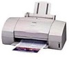
for easier ink level checking, contributing to lower running cost. Operator Panel Paper Guide Front Cover Paper Support Auto Sheet Feeder Paper Output Tray Paper Thickness Lever Parallel Interface Connector Cartridge Container Manual Feed Slot BJ Cartridges Figure 2-1 Printer Appearance 2-1 - Canon BJC 6000 | Service Manual - Page 32
BJC-6000 1.2 Features · Laser-printer quality using pigment black ink · Dual-cartridge system High quality printing at high speed from a combination of the Black and Color cartridges or the Color and Photo cartridges Black BJ cartridge: Drop modulation, replaceable ink tank (pigment black - Canon BJC 6000 | Service Manual - Page 33
BJC-6000 Part 2: Product Specifications 1.3 BJ Cartridge 1.3.1 Black BJ cartridge The Black BJ cartridge is to be mounted on the left side of the carriage for high speed color/monochrome printing. It is a disposable print head. It has 160 nozzles and accommodates a replaceable ink tank. It uses - Canon BJC 6000 | Service Manual - Page 34
Part 2: Product Specifications BJC-6000 1.3.3 Photo BJ cartridge The Photo BJ cartridge, mounted on the left side of the carriage for photo printing, is a disposable print head with 144 in-line nozzles, and accommodates replaceable photo-black, photo-magenta and photo-cyan ink tanks. It has 144 - Canon BJC 6000 | Service Manual - Page 35
BJC-6000 Part 2: Product Specifications 1.5 Consumables 1.5.1 Black, color, and photo BJ cartridges The Black, Color and Photo BJ cartridges for this printer are consumables. The BJ cartridges that come with your printer are identical to the BJ cartridges that are commercially available as - Canon BJC 6000 | Service Manual - Page 36
Part 2: Product Specifications BJC-6000 2. SPECIFICATIONS 2.1 General Specifications 1. Type Desktop serial color bubble-jet printer 2. Paper feeding method Automatic sheet feeder and manual sheet feed 3. Automatic sheet feeder capacity Plain paper: 13 mm max. stacking height (about 130 - Canon BJC 6000 | Service Manual - Page 37
BJC-6000 Part 2: Product Specifications 12. BJ cartridges Black BJ cartridge Construction: Print head: Ink: Cartridge service life: Ink tank: Ink tank service life: Cartridge weight: Separate ink tank type 160 nozzles, in-line Pigment black Approx. 5000 pages (1500-character, HQ mode) Black - Canon BJC 6000 | Service Manual - Page 38
for manual feed Thickness: max. 0.6 mm thick, max. 297 mm long Government Postcard weight: max. 190 g/m2, max. 0.23 mm thick Canon BJ printer High-resolution paper Glossy photo paper Glossy photo film Transparencies Back print film Banner paper (long type) Note: Fan-fold paper or label paper cannot - Canon BJC 6000 | Service Manual - Page 39
BJC-6000 3. Printable Area Part 2: Product Specifications A4, A5, and B5 sizes 3mm (1) 18.5mm (2) 12.0mm (2) 21.0mm 7.0mm (1) 22.6mm (2) 21.6mm 3.4mm 3.4mm Note: The printable area for thick paper is equa to that for postcards. 3.0mm 29.2mm Envelope 21.0mm 5.1mm A4+ 5.9mm Letter+ 5.1mm 7. - Canon BJC 6000 | Service Manual - Page 40
34 N.C.*2 17 GND ... 35 +5.0V*3 18 +5.0V*4 ... 36 SELECT IN *1: All RETs are connected to GND. *2: N.C. means no connection. *3: The level is pulled up with +5.0 V through a 3.3 k resistor. *4: The level is pulled up with +5.0 V through a 390 resistor. BJC-6000 I/O IN OUT IN 2-10 - Canon BJC 6000 | Service Manual - Page 41
BJC-6000 Part 2: Product Specifications Nibble mode No. Signal I/O No. 1 HostClk IN 19 2 ... 33 16 Gnd ... 34 17 Gnd ... 35 18 Vcc ... 36 *1: N.C. means no connection. Signal Signal Gnd Signal Gnd Signal Gnd Signal Gnd Signal Gnd Signal Gnd Signal Gnd Signal Gnd Signal - Canon BJC 6000 | Service Manual - Page 42
Part 2: Product Specifications BJC-6000 8) I/O signals Compatible Mode: STROBE (Input) This signal asks the printer to read Data 1 to Data 8. This signal becomes valid after the BUSY signal goes "L" and the printer outputs ACKNLG. This signal is normally "H," and the printer receives data after - Canon BJC 6000 | Service Manual - Page 43
BJC-6000 Part 2: Product Specifications SELECT IN (Input) When this signal is "H," the DC1/DC3 code is enabled; and when this signal is "L," the DC1/DC3 code is disabled. The printer reads this signal only at the time of power the printer supports the nibble mode. When the printer supports the - Canon BJC 6000 | Service Manual - Page 44
Part 2: Product Specifications BJC-6000 Data Avail (Output) In the reverse data transmission phase, the data. In the reverse data transmission phase, this signal is used to tell whether the data the printer has output on the data bus is command or data ("L" means command and "H," data). Ack Reverse - Canon BJC 6000 | Service Manual - Page 45
BJC-6000 Part 2: Product Specifications Host Ack (Input) When data is to be sent from the host computer to the printer, this signal is phase, this signal and Periph Clk perform handshaking. The host computer notifies the printer that it is ready to receive data by making this signal "L," and makes - Canon BJC 6000 | Service Manual - Page 46
Part 2: Product Specifications BJC-6000 1284 Active Ack Data Req Data (1~ 8) Host Busy Host Clk Ptr Clk Ptr Busy Data Avail Xflag Negotiation Setup Data Transmission (from printer to host computer) Bit2 Bit6 0000 0000 Printer Busy Status Bit3 Bit7 Bit0 Bit4 Bit1 Bit5 Figure 2-10 - Canon BJC 6000 | Service Manual - Page 47
INSTRUCTIONS Page 3- 1 3- 1 3- 2 3- 3 3 -10 3 -11 3 -11 3 -12 3 -12 3 -13 3 -14 3 -15 3 -16 3 -18 1. PRINTER SETUP 1.1 Unpacking 1.2 Installation Location 1.3 Installation 1.4 Names of Parts and Their Functions 2. TRANSPORTING THE PRINTER 2.1 Transporting the Printer 3. PRINTER SERVICE FUNCTIONS - Canon BJC 6000 | Service Manual - Page 48
- Canon BJC 6000 | Service Manual - Page 49
BJC-6000 Part 3: Operating Instructions 1. PRINTER SETUP 1.1 Unpacking After unpacking, make sure the items below are included: Quick Start Guide Ink Tanks Packing Packing Documentation BJ Cartridges Printer Cartridge Container Packing Tape Carton Packing Tape Tape Figure 3-1 Packaging - Canon BJC 6000 | Service Manual - Page 50
Part 3: Operating Instructions BJC-6000 1.2 Installation Location To ensure optimum performance, install the printer where there is adequate space. The figure below illustrates the printer's outside dimensions. Approx. 275 mm Approx. 470 mm Approx. 270 mm Approx. 195 mm Figure 3-2 Printer - Canon BJC 6000 | Service Manual - Page 51
the printer is in the initialization process. After initialization, the POWER lamp lights in green. If BJ cartridges are not installed, the POWER lamp lights in orange, the buzzer sounds six times, and the carriage moves to the cartridge replacement position. Figure 3-4 Connecting the Power Cord - Canon BJC 6000 | Service Manual - Page 52
Part 3: Operating Instructions BJC-6000 1.3.3 Installing the BJ cartridges This printer can be used with the Black, Color, and Photo BJ cartridges, in the following combinations : Black/Color BJ cartridges or Photo/Color BJ cartridges. a) Removing head protection from the BJ cartridges Remove the - Canon BJC 6000 | Service Manual - Page 53
BJC-6000 Part 3: Operating Instructions b) Installing the BJ cartridges Open the printer cover to install the BJ cartridges on the carriage. Install the Color BJ cartridge on the right side of the carriage. Install either the Black or Photo BJ cartridge on the left side of the carriage. After - Canon BJC 6000 | Service Manual - Page 54
Part 3: Operating Instructions BJC-6000 c) Installing the ink tanks Peel off the protective film from the ink tank, and slowly turn the protective cap off. Install the ink tanks in the BJ cartridges in the correct positions as indicated by the label affixed inside the printer. When the cover is - Canon BJC 6000 | Service Manual - Page 55
BJC-6000 Part 3: Operating Instructions e) Replacing the ink tanks For the Black, Color and Photo BJ cartridges, each ink tank can be individually replaced. 1) When to replace the ink tank Replace the ink tank with a new one if no ink can be seen inside, or as indicated by the ink-out alarm, or if - Canon BJC 6000 | Service Manual - Page 56
Part 3: Operating Instructions BJC-6000 f) Cartridge container This printer comes with a BJ cartridge container to store BJ cartridges. Once you have removed a BJ cartridge from the printer, store it in this cartridge container, ink tanks installed in place. If the BJ cartridge is left in open air - Canon BJC 6000 | Service Manual - Page 57
BJC-6000 Part 3: Operating Instructions 1.3.4 Aligning the print heads As there are two BJ cartridges installed in this printer, even a slight difference in size or seating position between them may result in inaccurate dot placement, and thereby poor printing. To correct this, after installing - Canon BJC 6000 | Service Manual - Page 58
Part 3: Operating Instructions 1.4 Names of Parts and Their Functions The main parts of the printer and their functions are illustrated below. BJC-6000 Paper Guide Lightly press this guide against the left side of paper sheets to align them. Front Cover Open this cover when replacing BJ cartridges - Canon BJC 6000 | Service Manual - Page 59
BJC-6000 Part 3: Operating Instructions 2. TRANSPORTING THE PRINTER When carrying or transporting the printer, keep BJ cartridges installed in the printer, or stored in the cartridge container. This prevents the ink from leaking or drying out in the nozzles during transportation. To prevent ink - Canon BJC 6000 | Service Manual - Page 60
to Part 5: 6 TROUBLESHOOTING (Page 5-13). TABLE 3-1 ERROR INDICATIONS Errors Indicator [Recoverable by user] Paper feed error Paper jam Ink out BJ cartridge mis-installed No BJ cartridge BJ cartridge error Waste ink warning Auto head adjustment error Lights in Orange Lights in Orange Lights in - Canon BJC 6000 | Service Manual - Page 61
BJC-6000 Part 3: Operating Instructions 3.2 Description of Error Indications Errors recoverable by users: 1) Paper feed error Paper feed operation fails to feed paper. 2) Paper jam error Paper eject operation of 23 inches still fails to eject the paper. 3) Ink out error The indicated ink tank is - Canon BJC 6000 | Service Manual - Page 62
Part 3: Operating Instructions BJC-6000 3.3 BJ Status Monitor The BJ status monitor window shows the printer's conditions and print-job progress. You can stop the print-job from this window. 3.3.1 Main functions of the BJ status monitor 1) Show the printer's conditions and progress in real-time by - Canon BJC 6000 | Service Manual - Page 63
BJC-6000 Part 3: Operating Instructions 3.4 Function Settings As this printer has no physical function selectors, function settings can be set by using the Canon printer driver. 3.4.1 Function settings using the printer driver The printer driver's utility menu allows such operations and function - Canon BJC 6000 | Service Manual - Page 64
or the manual feed slot, and print a standard pattern using all nozzles of both installed BJ cartridges. If print defects are detected in the test print, perform printhead cleaning. If five or more cleaning operations fail to solve the problem, replace the BJ cartridge with a new one. Use paper of - Canon BJC 6000 | Service Manual - Page 65
BJC-6000 Part 3: Operating Instructions Large dot printing Black 160 nozzles Small-dot printing Black BJ Cartridge Printed with the first nozzle Printed with the 160th nozzle Printed with the first nozzle Printed with the 160th nozzle Color BJ Cartridge Printed with the first nozzle Printed - Canon BJC 6000 | Service Manual - Page 66
Green Orange ... Model BJ F600 BJC-6000 Reserve Validate the model you have selected by pressing the POWER button. The buzzer will sound once. (The printer will switch off itself after performing the operation.) CAUTION Use the Black and Color BJ cartridges for the service/factory test printing - Canon BJC 6000 | Service Manual - Page 67
BJC-6000 Part 3: Operating Instructions 3.6.2 Service/factory test print The service/factory test print displays, in the header portion, such information as the control ROM version, model setting, total sheets passed, and total waste ink absorbed. Model ROM version Currently installed left and - Canon BJC 6000 | Service Manual - Page 68
Part 3: Operating Instructions BJC-6000 3.6.3 EEPROM information print The EEPROM stores such information as function settings, total sheets passed with the Black/Color or Photo/Color cartridges, total waste ink absorbed, and records the last three errors recoverable only by service personnel. The - Canon BJC 6000 | Service Manual - Page 69
BJC-6000 Part 3: Operating Instructions 3.6.4 Resetting EEPROM The EEPROM stores such information as function settings, total sheets passed with the Black/Color or Photo/Color cartridge, total waste ink absorbed, and the last three errors recoverable only by service personnel. Because the waste - Canon BJC 6000 | Service Manual - Page 70
Part 3: Operating Instructions BJC-6000 This page intentionally left blank 3-22 - Canon BJC 6000 | Service Manual - Page 71
2. FIRMWARE 2.1 Interface 2.2 Print Control 2.3 Automatic Printing Position Alignment Function 2.4 Pause Between Scanning 2.5 Pause Between Pages 2.6 Smear Control 2.7 Auto Power ON/OFF 2.8 Head Overheat Protection 3. PRINTER'S MECHANICAL SYSTEM 3.1 Overview 3.2 BJ Cartridge 3.3 Purge Unit 3.4 Paper - Canon BJC 6000 | Service Manual - Page 72
- Canon BJC 6000 | Service Manual - Page 73
BJC-6000 1. OVERVIEW 1.1 Printer Block Diagram Part 4: Technical Reference Purge Unit Purge Sensor ASF Unit Paper Feed Roller Print Position Sensor BJ Cartridge Carriage BJ Cartridge Paper Feed Drive Switching Unit Home Position Sensor Ink Sensor Paper Feed Motor CN602 CN603 Cover Sensor - Canon BJC 6000 | Service Manual - Page 74
Reference BJC-6000 1.2 Power On Sequence Flowchart This flowchart shows the initial sequence this printer goes through from power-on to on-line. AC Connection • Printer plugged In. Software initialization • MPU/printer controller initialized • ROM/RAM check • Ink sensor check • Waste ink full - Canon BJC 6000 | Service Manual - Page 75
BJC-6000 Part 4: Technical Reference 1.3 Flow of Print Signals The following outlines the flow of signals as the printer receives data from the host computer and prints it. a) The data from the host computer that contains control commands will be fed into the printer controller via the parallel - Canon BJC 6000 | Service Manual - Page 76
Part 4: Technical Reference BJC-6000 1.4 Print Driving The printer sends the control signals to the head in order to allow the head to discharge ink for printing. These signals consist of the drive control signals that cause ink to be discharged from the head nozzles, and the thermal control - Canon BJC 6000 | Service Manual - Page 77
BJC-6000 Part 4: Technical Reference b) Color/Photo BJ cartridge control The Color/Photo BJ cartridge drop. The head's 144 nozzles always fed to the head during printing, using the Block ENABLE cartridge's rear heater while HENB 1 and 3 drive its' front heater. HENB4 drives the Color BJ cartridge - Canon BJC 6000 | Service Manual - Page 78
Part 4: Technical Reference BJC-6000 1.4.2 Print drive method The head can be driven in one of the following six drive to turn on in the head nozzles. Note that the head type (Black BJ cartridge, Color BJ cartridge or Photo BJ cartridge) does not influence the type of print drive method. a) 360 x - Canon BJC 6000 | Service Manual - Page 79
BJC-6000 Part 4: Technical Reference b) 180 x180 dpi (large dot, forward direction) control mode In this mode, only 8 out of 16 nozzles in one block will be heated. This allows the carriage to travel faster than it would if all 16 nozzles were heated, resulting in faster printing. c) 360 x 360 dpi - Canon BJC 6000 | Service Manual - Page 80
Part 4: Technical Reference BJC-6000 g) Reverse direction print mode In the reverse direction print mode, printing determine the heating order are driven with timing reversed from that used in forward direction printing. HSEL2A0(Rear) HSEL2B0(Front) HSEL1A0(Rear) HSEL1B0(Front) 16 15 14 13 12 - Canon BJC 6000 | Service Manual - Page 81
BJC-6000 Part 4: Technical Reference 1.5 Power-Off Sequence Flowchart Beeper sounds once I/F busy set Indicator blinks Error reset When BJ cartridge or ink tank is replaced while replacing cartridge Cleaning operation • No cartridge • Capping in progress • While replacing cartridges, neither of - Canon BJC 6000 | Service Manual - Page 82
Part 4: Technical Reference BJC-6000 2. FIRMWARE 2.1 Interface This printer's interface supports compatible mode, nibble mode, data, including the device ID, printer status, etc. The printer uses the compatible mode or the ECP mode (forward transfer) when transferring print data. It should be noted - Canon BJC 6000 | Service Manual - Page 83
BJC-6000 Part 4: Technical Reference 2.1.2 Nibble mode The Nibble mode is used to transfer data to the host computer. It is in this mode that the printer sends the printer status data to the host computer. Four input control signals are used for data transfer with handshake between the PtrClk and - Canon BJC 6000 | Service Manual - Page 84
Part 4: Technical Reference BJC-6000 2.1.3 ECP mode The ECP mode allows data to be transferred bi-directionally between the printer and in (3) is received, the host computer causes HostAck to go high. (5) The printer causes AckReverse to go high to have the data recorded in the host computer. - Canon BJC 6000 | Service Manual - Page 85
BJC-6000 Part 4: Technical Reference 2.2 Print Control 2.2.1 Print mode The printer adjusts the carriage action and paper feed action according to the installed cartridges, selected print media, printing quality, print data, etc. to ensure high quality printing free from diffusion and density - Canon BJC 6000 | Service Manual - Page 86
Part 4: Technical Reference BJC-6000 TABLE 4-1 PRINT MODE LIST Regular Color Ink System (Black/Color BJ Cartridge) Paper High speed Standard (for speed) 180 x 180 (L) 360 x 360 (L) 2 2 Standard (for quality) 360 x 360 (L) 360 x 360 (L/S) 2 4 High quality Highest quality Printing mode - Canon BJC 6000 | Service Manual - Page 87
BJC-6000 Part 4: Technical Reference 2.3 Automatic Printing Position Alignment Function This printer features the automatic printing position alignment function so that the difference between the installed left and right BJ cartridges in vertical/horizontal printing position and bi-directional - Canon BJC 6000 | Service Manual - Page 88
data from the host computer. If, however, an error exists, paper is in the manual feed slot, or the front cover is open, the printer will not power off. 2.8 Head Overheat Protection If the printer continues to print after ink has run-out, the bubble jet head will overheat. To prevent this, when the - Canon BJC 6000 | Service Manual - Page 89
BJC-6000 Part 4: Technical Reference 3. PRINTER'S MECHANICAL SYSTEM 3.1 Overview The printer's mechanical system is comprised of the BJ cartridges, carriage unit, purge unit, paper-feed unit, and drive switching unit. The following describes each of these units: Paper Feed Unit Carriage Unit - Canon BJC 6000 | Service Manual - Page 90
to the paper feed unit). Paper feed unit The paper feed unit, driven by the paper feed motor, turns the feed roller to horizontally move the paper beneath the BJ cartridge print head while keeping the paper level on the platen without cockling. To manually feed paper through this printer, use the - Canon BJC 6000 | Service Manual - Page 91
BJC-6000 Part 4: Technical Reference 3.2. BJ Cartridge 3.2.1 Construction of the Black BJ cartridge The Black BJ cartridge has a 160-nozzle multi-drop bubble jet head and a detachable black ink tank. a) Air path Keeps the pressure inside the ink tank constant with the external atmospheric pressure - Canon BJC 6000 | Service Manual - Page 92
Part 4: Technical Reference BJC-6000 3.2.2 Construction of the Color and Photo BJ cartridges Color and Photo BJ Cartridges come equipped with a multi-drop bubble jet head comprised of 48 nozzles for each of the three colors, for a total of 144 nozzles, and have separate, detachable ink tanks, one - Canon BJC 6000 | Service Manual - Page 93
BJC-6000 Part 4: Technical Reference 3.2.3 Construction of the bubble jet head unit a) Bubble jet nozzle Ink absorbed in the ink sponge will be filtered through the mesh ink filter, then fed to the bubble jet nozzles via ink pipes. When the head drive current passes through a heater board in a - Canon BJC 6000 | Service Manual - Page 94
Part 4: Technical Reference BJC-6000 b) Nozzle arrangement The bubble jet nozzles are lined up vertically at 1/360 inch pitch in one column. Color and Photo BJ cartridge have 8 dummy nozzles separating the nozzles of each color. Black BJ Cartridge Photo BJ Cartridge 160th nozzle 160th nozzle - Canon BJC 6000 | Service Manual - Page 95
OUT Reset signal 30 DIA0 IN Head temperature (diode) sensor's anode line (DIA1) 31 DIK0 IN Head temperature (diode) sensor's cathode line (DIK1) 32 ... ... Not used The bracketed signal name (.....) is the name used for Color/Photo BJ cartridge if different from that used for Black BJ - Canon BJC 6000 | Service Manual - Page 96
Part 4: Technical Reference BJC-6000 d) Cartridge identification This printer uses 5 signals, HCLOCK (Pin 13), HDATA (Pin 9), HLAT (Pin 19), HRSTX (Pin 29), and DIR (Pin 28) to communicate serially with the bubble jet head to identify the installed BJ cartridge and the head rank. Bubble jet head - Canon BJC 6000 | Service Manual - Page 97
mechanism becomes activated in the following cases to help maintain high quality printing. Printer Status Reference Ink Consumption (mg) Black Color Photo Power ON Initial power on (1 time only) 0.49 0.75 0.75 Switched on for the 1st time since connecting to AC (capped) 0.19 0.27 0.27 Switched - Canon BJC 6000 | Service Manual - Page 98
Part 4: Technical Reference 3.3.2 Construction of the purge unit BJC-6000 Wiper Release Unit Cap Unit Wiper Unit Carriage Lock Unit Purge Drive Gear Pump Unit Air Valve Unit Figure 4-20 Purge Unit a) Purge drive gear Receives the power of the feed roller driven by the paper feed motor via the - Canon BJC 6000 | Service Manual - Page 99
Cap Open Close Reverse Turning (Color BJ Cartridge) Pressure Rollers Pump Unit Air Valve Ink Tube Waste Ink Carriage Black / Photo BJ Cartridge Open Close Forward Turning (Black/Photo BJ Cartridge) Pressure Roller Air Valve Pump Unit Waste Ink Ink Tube Figure 4-21 Pumping Operations - Canon BJC 6000 | Service Manual - Page 100
BJC-6000 3.4 Paper Feed Unit 3.4.1 Functions of the paper feed unit a) Paper feed function This printer has two paper supply methods, using the auto-sheet feeder in automatic paper feed mode, or the manual feed slot. The built-in auto-sheet feeder, driven by the paper feed motor and loaded - Canon BJC 6000 | Service Manual - Page 101
BJC-6000 Part 4: Technical Reference b) Paper thickness adjustment The clearance between the head face of the BJ cartridge and the paper varies with the thickness of the paper. Smaller clearance improves the printing quality however, paper contacting the head face risks spoiling print quality or - Canon BJC 6000 | Service Manual - Page 102
BJC-6000 3.4.2 Construction of the paper feed unit This printer's paper feed unit is mechanically comprised of the pick-up unit, paper feed unit, and the paper eject unit. a) Pick-up unit Pick-up Roller Paper Pick-up Hook Pick-up Corner Pick-up Guide Stacked Paper Manual Paper Feeding - Canon BJC 6000 | Service Manual - Page 103
BJC-6000 Part 4: Technical Reference To manually feed paper, the user must insert the paper into the manual feed slot until the paper end sensor detects it. In the manual paper feed mode, the pick-up guide changes its position for the paper to pass through a different path from that in which the - Canon BJC 6000 | Service Manual - Page 104
Part 4: Technical Reference BJC-6000 3.5 Carriage Unit 3.5.1 Functions of carriage unit a) Mounting BJ cartridges The carriage secures BJ cartridges mechanically in place and connects them via the carriage ribbon cable to the control board. When the printer is powered off, the carriage will be - Canon BJC 6000 | Service Manual - Page 105
BJC-6000 Part 4: Technical Reference 3.5.2 Construction of the carriage unit Carriage Ribbon Cable BJ Cartridge Mount Home Position Edge Carriage Lock Position Edge Signal Contacts Carriage Belt Carriage Motor Figure 4-26 Carriage Unit a) BJ cartridge mount BJ cartridges are secured to the - Canon BJC 6000 | Service Manual - Page 106
Part 4: Technical Reference BJC-6000 c) BJ cartridge maintenance By controlling the carriage position, wiping and cleaning operations will be performed on the BJ cartridge. During capping, as the carriage travels left to right, the notch on the carriage causes the purge section wiper flag to move, - Canon BJC 6000 | Service Manual - Page 107
BJC-6000 Part 4: Technical Reference d) Paper feed motor drive switching unit Depending on the carriage position, the drive switching unit switches the paper feed motor's drive power over to drive the purge unit or the auto-sheet feeder. The slide arm that travels in sync with the carriage action - Canon BJC 6000 | Service Manual - Page 108
Part 4: Technical Reference BJC-6000 4 PRINTER'S ELECTRICAL SYSTEM 4.1 Overview The electronics of this printer can be functionally divided into the control unit and the power supply unit. The control section converts the input data from the host computer into print signals or printer control - Canon BJC 6000 | Service Manual - Page 109
DIR HENB0K*5 SUBH0,1 PC3 2 Kbit PB EEPROM 0~3 Driver IC PC1 Paper End Sensor PA1 Error Indicator Power Indicator Home Position Sensor BJ Cartridge Connector BJ Cartridge Connector Pump Sensor PM Carriage Motor PM Paper Feed Motor BJ Cartridges Parallel Interface Figure 4-31 Control Unit - Canon BJC 6000 | Service Manual - Page 110
LED POWER Switch Cover Sensor ROM BJC-6000 CN603 CN402 CN602 CN404 CN403 Motor Driver Printer Controller Buzzer Paper End Sensor DRAM EEPROM MPU TH201 Figure 4-33 Control Board a) Printer controller The printer controller incorporates the interface controller, print head controller - Canon BJC 6000 | Service Manual - Page 111
from the reset IC. I/O port Sends indicator lighting and the power supply voltage output control signals as output signals, receives sensor signals from the home position sensor, pump sensor, and paper end sensor as input signals, controls the EEPROM data I/O, and sends the motor driver reset signal - Canon BJC 6000 | Service Manual - Page 112
sends the lighting signal for the LED inside the print position sensor as output. c) DRAM (IC302) Controlled by the printer controller, the 16Mbit-DRAM is used as a receive buffer, download buffer, print buffer, and working area. d) Motor driver IC (IC401) Drives carriage motor and paper feed motor - Canon BJC 6000 | Service Manual - Page 113
BJC-6000 4.3 Power Supply Unit 4.3.1 Power Supply Unit Block Diagram Part 4: Technical Reference AC100V +24V DC Carriage Motor (VM) Paper Feed Motor (VM) BJ Cartridge (HVH) HVCONT(+24VDC output control signal) AC Adapter DC/DC Converter EEPROM Printer Controller +5V DC Control ROM +3V RGV3/ - Canon BJC 6000 | Service Manual - Page 114
Part 4: Technical Reference 5. DETECTION FUNCTIONS 5.1 Detection with Sensors This printer has the following sensors detect the printer's status. Cover Sensor Paper End Sensor BJC-6000 Internal Temperature Sensor Pump Sensor Ink Sensor Print Position Sensor Home Position Sensor Figure 4-35 - Canon BJC 6000 | Service Manual - Page 115
BJC-6000 Part 4: Technical Reference 5.1.4 Ink sensor Consists of an LED and photosensor to optically check for ink in the ink chamber part of the ink tank. At the ink chamber bottom is a protrusion that acts as a prism. If ink is present in the chamber, the refraction rates of ink and the prism - Canon BJC 6000 | Service Manual - Page 116
for evaporated ink, a waste ink warning will be issued on power-up. If this condition continues until the estimated waste ink amount reaches 100%, a "Waste Ink Full" error will be issued. 5.2.2 BJ cartridge detection The detection signals from the index unit, built into the print head heater board - Canon BJC 6000 | Service Manual - Page 117
6.1 Troubleshooting Overview 6.2 Diagnosis 7. CONNECTOR POSITIONS AND PIN ASS 7.1 Control Board 7.2 Carriage Board 7.3 BJ Cartridge 7.4 AC adapter 7.5 DC power supply cable 7.6 Carriage Motor 7.7 Paper Feed Motor 7.8 Ink Sensor 7.9 Print Position Sensor 7.10Pump Sensor 8. CIRCUIT DIAGRAMS 8.1 Parts - Canon BJC 6000 | Service Manual - Page 118
- Canon BJC 6000 | Service Manual - Page 119
BJC-6000 Part 5: Maintenance 1. MAINTENANCE 1.1 Parts for Periodic Replacement Level User Service personnel None None Parts for periodic replacement 1.2 List of Consumables (for details, see Part 2: 1-5 Consumables (page 2-5) Level User Service personnel Consumable Black BJ cartridge Color - Canon BJC 6000 | Service Manual - Page 120
Part 5: Maintenance BJC-6000 2. SERVICE TOOLS 2.1 List of Tools Ordinary Tools Phillips installing flexible cables For applying grease (one per grease type) For applying FLOIL 946P For troubleshooting Special Tools (part No.) 1.9-mm gap gauge (QY9-0038-000) 0.5-mm gap gauge (QY9-0001- - Canon BJC 6000 | Service Manual - Page 121
BJC-6000 Part 5: Maintenance 3. APPLYING GREASE Apply greases at the points shown below. Apply a thin film of grease using the flat brush. For the Carriage Oil Pad, do not use a brush but apply directly. For disassembly and reassembly procedures, refer to the parts catalog. CAUTION Be careful not - Canon BJC 6000 | Service Manual - Page 122
Part 5: Maintenance BJC-6000 4. DISASSEMBLY AND REASSEMBLY 4.1 Disassembly and Reassembly When disassembling or reassembling the printer, refer to the parts catalog. The numbers in the parts catalog illustrations indicate the disassembly sequence. The parts catalog also contains close-up diagrams - Canon BJC 6000 | Service Manual - Page 123
BJC-6000 Part 5: Maintenance 4.2.2 Removing the printer unit Refer to Figure 5 (page B-9) of the parts catalog. 1) Set the paper thickness lever to its lowest position (envelope position). 2) Press the locking tab on the right side of the printer in the direction of arrow 1 and slightly lift the - Canon BJC 6000 | Service Manual - Page 124
Part 5: Maintenance BJC-6000 4.2.3 Removing the ASF unit The ASF unit is attached to the printer unit supporting the carriage shaft The adjustable bearings supporting the carriage shaft are adjusted and secured to the printer frame so that the ideal head-to-paper gap is maintained for best print - Canon BJC 6000 | Service Manual - Page 125
BJC-6000 Part 5: Maintenance 4.2.5 Paper feed gears Be careful not to touch the gears in the paper feed unit, especially the paper feed gear, during disassembly or reassembly, because even slight damage to it could affect paper feeding when printing at high resolution. Eject Roller Gear Feed - Canon BJC 6000 | Service Manual - Page 126
Part 5: Maintenance BJC-6000 5. ADJUSTMENTS AND SETTINGS 5.1 Adjustments and Settings 5.1.1 EEPROM setting 1) When the control board is replaced (see Figure 4 of the parts catalog). 2) When the waste ink absorber is replaced (see Figure 6 of the parts catalog). 5.1.2 Carriage belt tension - Canon BJC 6000 | Service Manual - Page 127
to Part 3: 3.6.1 Service mode operations (page 3-18). NOTE The waste ink full error should not normally occur before the printer's designed life expires (as counted by printed sheets). The error may occur, however, if the printer has been switched on and off very often, the BJ cartridges have - Canon BJC 6000 | Service Manual - Page 128
Part 5: Maintenance BJC-6000 5.2.3 ASF gear position adjustment Preparation: 1) Reassemble the ASF unit components to the level as when the ASF unit was detached. Adjustment procedure: 1) Set the gear key special tool (QY9-0038-000) to the paper eject roller gear. 2) Turn the gear key half a turn - Canon BJC 6000 | Service Manual - Page 129
BJC-6000 Part 5: Maintenance 5.2.4 Head gap adjustment Preparation: 1) Reassemble to the level the top cover is to be put on next. 2) Raise both the right and left adjustable bearings supporting the carriage shaft in the direction of arrow 1, and temporarily fix the bearings in that position using - Canon BJC 6000 | Service Manual - Page 130
Part 5: Maintenance BJC-6000 Adjustment procedure: 1) Set the 1.9-mm gap gauge (QY9-0038) in position A. 2) Move the carriage into position C by moving the carriage belt by hand. 3) Install the Black BJ cartridge on the left side of the carriage. 4) Slowly loosen, by half a turn, the fixing screw - Canon BJC 6000 | Service Manual - Page 131
a part, be sure to make a test print to check that the problem is corrected. If the indicated measures of a specific step still fail to correct the trouble, try again, skipping to the next step. Example 1 Do print problems No appear? Yes 1. Replace the ink tank 2. Replace the BJ cartridge END - Canon BJC 6000 | Service Manual - Page 132
one as measure 1, and make a test print to see if the problem is corrected. If not, replace the whole BJ cartridge as measure 2. Do print problems No appear? Yes END 1. Replace the ink tank 2. Replace the BJ cartridge 6. After concluding troubleshooting, ensure that all connectors and screws are - Canon BJC 6000 | Service Manual - Page 133
BJC-6000 6.2 Diagnosis 6.2.1 Initial flowchart Part 5: Maintenance Plug in the AC cord • The printer is supplied with AC power. MPU/printer controller initialization ROM check DRAM check Ink sensor/waste ink full/printer temperature sensor (TH201) check Read EEPROM Turn power on • The POWER - Canon BJC 6000 | Service Manual - Page 134
Part 5: Maintenance BJC-6000 From previous page Error check OK? Yes No EEPROM error ROM error Diode sensor check RAM error Waste ink full error Printer temperature sensor error • 10 beeps, indicator blinks in orange 3 times (See page 5-18) • 10 beeps, indicator blinks in orange 1 time (See - Canon BJC 6000 | Service Manual - Page 135
BJC-6000 From previous page BJ cartridge check OK? No Yes Cleaning Part 5: Maintenance Check for open cover • Is the cover open? Open/closed Closed Open Carriage moves to cartridge replacement position • Cartridge installed • Cartridge not detected • Cartridge not installed correctly I/F - Canon BJC 6000 | Service Manual - Page 136
> RAM cannot be read or written. DRAM, print controller Replace the control board. 3. EEPROM Error EEPROM cannot be written. EEPROM, print controller Replace the control board. BJC-6000 CAUTION Error indications may fail if the ROM - Canon BJC 6000 | Service Manual - Page 137
BJC-6000 Part 5: Maintenance 4. Home Position Error The home position sensor fails to detect the home position. Home position sensor, carriage motor, paper feed motor, control board, carriage ribbon cable, and carriage board Visual check OK? Yes No Repair or - Canon BJC 6000 | Service Manual - Page 138
Part 5: Maintenance From previous page Visually check operation of paper feed unit OK? Yes No Check the paper feed motor BJC-6000 1 4 OK? Yes To page 5-21 (1) Measurement points Normal value CN403 Pin 1-3 2-4 Approx.3 Disconnect the paper feed motor cable from the control board before - Canon BJC 6000 | Service Manual - Page 139
BJC-6000 Part 5: Maintenance (1) HVCONT check HVCONT (+24 VDC output control signal) for output (CN401). +5VDC HVCONT GND +24VDC GND OK? Yes No Replace the control board +24 - Canon BJC 6000 | Service Manual - Page 140
> Replace the control board. BJC-6000 6. Waste Ink Full Error The calculated amount of waste ink absorbed has exceeded the capacity of the waste ink absorber. Waste ink absorber, control board 1. Reset the EEPROM/replace the waste ink absorber. 2. Replace the - Canon BJC 6000 | Service Manual - Page 141
BJC-6000 Part 5: Maintenance 7. Head Temperature Error/Head Temperature Sensor Error The print head is too hot. BJ cartridge, control board Leave the printer for several It is possible the BJ cartridge head unit minutes with power off has overheated. Turn - Canon BJC 6000 | Service Manual - Page 142
Displaced Error Remove and reinstall both BJ cartridges BJC-6000 The BJ cartridge is out of position at other than the cartridge replacement position. BJ cartridge, control board, carriage board, carriage ribbon cable Error indication? No Yes 1. Replace - Canon BJC 6000 | Service Manual - Page 143
BJC-6000 Part 5: Maintenance 9. Paper Feed Error • Paper feed operation fails to feed paper. • Paper eject operation fails to eject paper. Paper feed section, paper end sensor, control board Visually check the paper feed unit Check for jammed paper or - Canon BJC 6000 | Service Manual - Page 144
Part 5: Maintenance From previous page BJC-6000 Paper End Sensor Sensor Flag Paper ASF Feed Path Manual Feed Path Check the paper end sensor's arm Using paper, check the arm for smooth motion, deformation, or damage. OK? Yes No Replace the sensor arm Paper sensor check Measurementpoints - Canon BJC 6000 | Service Manual - Page 145
BJC-6000 Part 5: Maintenance • The ink tank is empty. 10. Ink Out Error • EEPROM is defective. Ink tank, EEPROM Visually check that the ink tanks are installed OK? Yes No Install ink tanks Replace the control board 5-27 - Canon BJC 6000 | Service Manual - Page 146
Part 5: Maintenance BJC-6000 11. BJ Cartridge Error/BJ Cartridge Misinstalled Error/No BJ Cartridge Error • BJ cartridge not detected. • BJ cartridge not installed. • BJ cartridge combination wrong. BJ cartridges, carriage board, control board, carriage ribbon cable, - Canon BJC 6000 | Service Manual - Page 147
parts> BJ cartridge, ink tank, print position sensor, control board Is the automatic head position adjustment pattern correctly printed? OK? Yes No 1. Cleaning Print position sensor check 2. Replace the ink tank • Black/cyan ink tank 3. Replace the BJ cartridge • Black/Color - Canon BJC 6000 | Service Manual - Page 148
Part 5: Maintenance BJC-6000 b) Phenomena 1. Power Does Not Turn On. • Pressing the POWER button fails to switch on the printer. • Pressing the POWER button does not start initialization. The AC adapter or the control board is defective. Check the AC adapter for +5 - Canon BJC 6000 | Service Manual - Page 149
BJC-6000 Part 5: Maintenance 2. Faulty Printing: No Printing • No prints • Partial prints • No prints for some colors The ink tank, BJ cartridge, or purge unit is defective. Cleaning operation Perform the cleaning operation 5 times. Nozzle check pattern See Part - Canon BJC 6000 | Service Manual - Page 150
Perform the cleaning operation 5 times. Nozzle check pattern See Part 3: 3.5.2 Nozzle check pattern printing (page 3-16) Do print problems No appear? Yes 1. Replace the relevant ink tank 2. Replace the relevant BJ cartridge END Do print problems No still appear? Yes END To next page 5-32 - Canon BJC 6000 | Service Manual - Page 151
BJC-6000 From previous page 1. Replace the carriage ribbon cable 2. Replace the carriage board 3. Replace the control board OK? Yes No Replace the purge unit END Part 5: Maintenance 5-33 - Canon BJC 6000 | Service Manual - Page 152
Part 5: Maintenance BJC-6000 4. Faulty Printing: Other Symptoms Paper gets dirty Spur marks appear Vertical misalignment Check to see if Measure The platen is contaminated with Wipe clean with a damp cloth. ink mist. The paper feed unit is Disassemble the paper feed unit contaminated with - Canon BJC 6000 | Service Manual - Page 153
BJC-6000 Part 5: Maintenance 5. Ink Out Resulting in no Error Ink out results in no error. The ink tank is empty, or the control board or ink sensor is defective. Visually check the ink No ink tank? Any loose ink tank? Ink tanks chamber empty? OK? Yes No Replace - Canon BJC 6000 | Service Manual - Page 154
Part 5: Maintenance BJC-6000 7. CONNECTOR POSITIONS AND PIN ASSIGNMENT 7.1 Control Board 1 52 3 CN603 CN402 CN602 1 CN401 1 4 1 1 19 CN404 1 CN403 4 18 36 Figure 5-11 Control Board CN404 (parallel interface connector) - Canon BJC 6000 | Service Manual - Page 155
4 LFB OUT Paper feed motor phase B Part 5: Maintenance CN501 (Carriage ribbon cable connector) Pin No. 1~8 9, 10, 11 12, 13, 14 15~22 23, 24, 25 26~28 Signal HVH SUBH0 SUBH1 ... HVDD IN/OUT OUT OUT OUT ... OUT Function Head drive voltage (VH) Sub-heater drive voltage (for left cartridge) Sub - Canon BJC 6000 | Service Manual - Page 156
Part 5: Maintenance BJC-6000 CN502 (Carriage ribbon cable for serial data transmission ... GND IN/OUT Serial data (left cartridge) sent in sync. with the clock signal OUT Rear nozzle heater signal OUT Reset signal ... GND IN Head temperature (diode) sensor's anode line IN Head temperature ( - Canon BJC 6000 | Service Manual - Page 157
BJC-6000 Part 5: Maintenance CN602 (Pump sensor connector) Pin No. 1 2 Signal POMP ... IN/OUT Function IN Pump sensor sense signal High (sense) /Low ... GND CN603 (Ink sensor connector) Pin No. 1 2 3 Signal INKS01 ... INKS IN/OUT OUT ... IN Function Voltage output from the ink sensor - Canon BJC 6000 | Service Manual - Page 158
Part 5: Maintenance 7.2 Carriage Board 4 2 CN4 32 4 34 2 32 CN5 34 BJC-6000 1 3 31 33 1 3 31 33 1 CN1 27 1 CN3 18 power supply. Head logic drive voltage GND for head drive voltage (VH) Sub-heater drive voltage (for right cartridge) Sub-heater drive voltage (for left cartridge) Head - Canon BJC 6000 | Service Manual - Page 159
BJC-6000 Part Print position sensor's LED drive voltage OUT Home position sensor sense signal IN Home position sensor pull-up voltage OUT Head temperature (diode) sensor's cathode line OUT Head temperature (diode) sensor's anode line IN GND IN Reset for the logic power supply IN Front nozzle - Canon BJC 6000 | Service Manual - Page 160
Part 5: Maintenance BJC-6000 CN3 (Carriage ribbon cable connector) Pin No. 1 2 3 4 5 6, 8 7, 9 10, 15, 17 11 12 13 14 16 18 Signal ... N.C. DIK1 DIA1 SNSG HENB5 HENB4 LGND HSEL2B1 HSEL2A1 HSEL1B1 HSEL1A1 HDATA1 HCLOCK1 IN/OUT Function ... Not used ... N.C. IN Head temperature (diode) sensor - Canon BJC 6000 | Service Manual - Page 161
BJC-6000 7.3 BJ Cartridge Part 5: Maintenance 32 28 24 20 16 12 8 4 30 26 22 18 14 10 6 2 31 27 23 19 -160 OUT OUT IN IN ... Serial data input/output direction control signal Reset signal Head temperature (diode) sensor's anode line Head temperature (diode) sensor's cathode line Not used. 5-43 - Canon BJC 6000 | Service Manual - Page 162
Part 5: Maintenance 7.4 AC Adapter BJC-6000 1 7 2 8 Pin No. 1 2 3 4 5 6 7 8 Signal ... ... ... GND ... ... HVCONT GND Figure 5-14 AC Adapter IN/OUT OUT ... IN ... Function N.C N.C +24V DC GND +5V DC N.C +24 V control signal GND 7.5 DC Power Supply Cable 5 2 1 3 1 2 4 5 Pin No. - Canon BJC 6000 | Service Manual - Page 163
BJC-6000 7.6 Carriage Motor Part 5: Maintenance 1 4 Pin No. 1 2 3 4 Signal CRA CRB CRA CRB Figure 5-16 Carriage Motor IN/OUT IN IN IN IN Function Carriage motor phase A Carriage motor phase B Carriage motor phase A Carriage motor phase B 7.7 Paper Feed Motor 1 4 Pin No. 1 2 3 4 Signal LFA - Canon BJC 6000 | Service Manual - Page 164
Part 5: Maintenance 7.8 Ink Sensor BJC-6000 1 3 13 13 Pin No. 1 2 3 Signal INKS01 ... ... Figure 5-18 Ink Sensor IN/OUT OUT ... ... Function Voltage output from the ink sensor GND N.C. 7.9 Print Position Sensor 1 4 Pin No. 1 2 3 4 Signal REGA SNSG REGC LGND Figure 5-19 Print Position - Canon BJC 6000 | Service Manual - Page 165
BJC-6000 8. CIRCUIT DIAGRAMS 8.1 Parts Layout 8.1.1 Control board Part 5: Maintenance Figure 5-21 Control Board 5-47 - Canon BJC 6000 | Service Manual - Page 166
Part 5: Maintenance 8.1.2 Carriage board BJC-6000 Figure 5-22 Carriage Board 5-48 - Canon BJC 6000 | Service Manual - Page 167
BJC-6000 8.2 Circuit Diagrams 8 7 REG1 RGV5 C206 0.1m,25V RGV3 1 2 RGV3 2 1 0 16 D POW SW 4 INT Part 5: Maintenance 3 2 VSEN1 1 CONTROL BOARD 01 Q605 CN603 Ink Sensor Q608 FA1L4M FN1A4P R611 150.1/4W 3 3 F R618 110K,1/16W 2 2 R613 - Canon BJC 6000 | Service Manual - Page 168
BJC-6000 Part 5: Maintenance 8 7 A11 A10 SV VDD VSS VSS Printer Controller IC301 UPD82634GD-001-ML Buttons A 22 987654321 4 RGV5 EEPROM(2Kbit) IC602 5-2922DAFJ 2 RCS Indicator RGV51 LED601 R609 POWER(GREEN) 180.1/10W SEC2494C R610 RESUME(ORANGE) 180.1/10W VSEN1 - Canon BJC 6000 | Service Manual - Page 169
,1/16W, D,1608 R510 180K,1/16W, D,1608 R511 7.5K,1/16W, D,1608 BJC-6000 8 7 6 5 4 3 HEADCONT 2 22 C505 R529 33,1/16W 0.01m,50V TOPC PW C Q505 FA1L4H Part 5: Maintenance 2 1 CONTROL BOARD 03 HEAD 0 CN502 1 HCLOCK0 2 3 HDATA0 F 4 5 HSEL1A0 6 HSEL1B0 7 - Canon BJC 6000 | Service Manual - Page 170
BJC-6000 Part 47K,1/16W HVDD VM R423 1,4,1/4W,G, 3216 Driver IC401 TB62200F RGV51 VM R424 1.5,1/4W R418 33 VIF 3. A CLK AB 30 8 CR AB DATA AB 29 9 VREF AB RESET 28 37 VSS VSS 38 10 BREF CD VDD 27 11 CR CD Paper Feed Motor C422 100p,50V C423 100p,50V C424 100p,50V C425 100p - Canon BJC 6000 | Service Manual - Page 171
BJC-6000 1 3 2 REGC 1 RANK0 2 4 Home Position Sensor C4 0.1m,50V 05 Print Position CN6 Sensor 1 REGA 1 2 2 SNSG 3 REGC 4 LGND 3,4 CN4 1 8 HENB5 7 HENB4 6 HENB5 5 SNSG 4 DIA1 3 DIK1 2 N.C. 1 RNAK1 Part 5: Maintenance 2 1 CARRIAGE BOARD 05 F E D C5 0.1m,50V CN5 1 HVH - Canon BJC 6000 | Service Manual - Page 172
- Canon BJC 6000 | Service Manual - Page 173
- Canon BJC 6000 | Service Manual - Page 174
The printing paper contains 70% waste paper. PRINTED IN JAPAN (IMPRIME AU JAPON) CANON INC.
-
 1
1 -
 2
2 -
 3
3 -
 4
4 -
 5
5 -
 6
6 -
 7
7 -
8
-
9
-
10
-
11
-
12
-
13
-
14
-
15
-
16
-
17
-
18
-
19
-
20
-
21
-
22
-
23
-
24
-
25
-
26
-
27
-
28
-
29
-
30
-
31
-
32
-
33
-
34
-
35
-
36
-
37
-
38
-
39
-
40
-
41
-
42
-
43
-
44
-
45
-
46
-
47
-
48
-
49
-
50
-
51
-
52
-
53
-
54
-
55
-
56
-
57
-
58
-
59
-
60
-
61
-
62
-
63
-
64
-
65
-
66
-
67
-
68
-
69
-
70
-
71
-
72
-
73
-
74
-
75
-
76
-
77
-
78
-
79
-
80
-
81
-
82
-
83
-
84
-
85
-
86
-
87
-
88
-
89
-
90
-
91
-
92
-
93
-
94
-
95
-
96
-
97
-
98
-
99
-
100
-
101
-
102
-
103
-
104
-
105
-
106
-
107
-
108
-
109
-
110
-
111
-
112
-
113
-
114
-
115
-
116
-
117
-
118
-
119
-
120
-
121
-
122
-
123
-
124
-
125
-
126
-
127
-
128
-
129
-
130
-
131
-
132
-
133
-
134
-
135
-
136
-
137
-
138
-
139
-
140
-
141
-
142
-
143
-
144
-
145
-
146
-
147
-
148
-
149
-
150
-
151
-
152
-
153
-
154
-
155
-
156
-
157
-
158
-
159
-
160
-
161
-
162
-
163
-
164
-
165
-
166
-
167
-
168
-
169
-
170
-
171
-
172
-
173
-
174
 |
 |
QY8-1361-000
JAN. 1999
COPYRIGHT
1999 CANON INC.
CANON BJC-6000 SE 0199 0.30-0 PRINTED IN JAPAN (IMPRIME AU JAPON)
REVISION 0