Canon BJC 6000 Service Manual - Page 107
Operation of the Drive Switching Unit, Drive Switching Unit, Slide Arm
 |
View all Canon BJC 6000 manuals
Add to My Manuals
Save this manual to your list of manuals |
Page 107 highlights
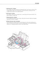
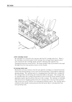
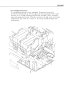
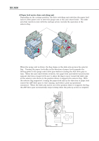
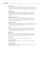
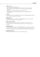
BJC-6000 Part 4: Technical Reference d) Paper feed motor drive switching unit Depending on the carriage position, the drive switching unit switches the paper feed motor's drive power over to drive the purge unit or the auto-sheet feeder. The slide arm that travels in sync with the carriage action controls the operation of the selector flag. Slide Arm Flag Clamp Selector Flag Drive Input Gear ASF Drive Gear Figure 4-28 Drive Switching Unit Purge Drive Gear When the purge unit is driven, the flag clamp on the slide arm secures the selector flag. Turning the paper feed roller in the direction of paper feed transmits the driving power to the purge unit's drive gear without causing the ASF drive gear to turn. When the auto-sheet feeder is driven, the paper feed unit will be turned in the opposite direction of paper feed once to allow the flag to move toward the slide arm as the selector arm moves to the position where it supports the selector flag. With the selector flag supported, turning the paper feed unit in the direction of paper feed causes the ASF drive gear to start turning, and with it, pick-up operations commence. When the slide arm moves out of the position where it supports the flag, the ASF drive gear automatically stops turning when the pick-up action is complete. Slide Arm Selector Flag (when ASF is driven) Selector Flag (when purge is driven) Figure 4-29 Operation of the Drive Switching Unit 4-35
-
 1
1 -
2
-
3
-
4
-
5
-
6
-
7
-
8
-
9
-
10
-
11
-
12
-
13
-
14
-
15
-
16
-
17
-
18
-
19
-
20
-
21
-
22
-
23
-
24
-
25
-
26
-
27
-
28
-
29
-
30
-
31
-
32
-
33
-
34
-
35
-
36
-
37
-
38
-
39
-
40
-
41
-
42
-
43
-
44
-
45
-
46
-
47
-
48
-
49
-
50
-
51
-
52
-
53
-
54
-
55
-
56
-
57
-
58
-
59
-
60
-
61
-
62
-
63
-
64
-
65
-
66
-
67
-
68
-
69
-
70
-
71
-
72
-
73
-
74
-
75
-
76
-
77
-
78
-
79
-
80
-
81
-
82
-
83
-
84
-
85
-
86
-
87
-
88
-
89
-
90
-
91
-
92
-
93
-
94
-
95
-
96
-
97
-
98
-
99
-
100
-
101
-
 102
102 -
 103
103 -
 104
104 -
 105
105 -
 106
106 -
 107
107 -
 108
108 -
 109
109 -
 110
110 -
 111
111 -
 112
112 -
113
-
114
-
115
-
116
-
117
-
118
-
119
-
120
-
121
-
122
-
123
-
124
-
125
-
126
-
127
-
128
-
129
-
130
-
131
-
132
-
133
-
134
-
135
-
136
-
137
-
138
-
139
-
140
-
141
-
142
-
143
-
144
-
145
-
146
-
147
-
148
-
149
-
150
-
151
-
152
-
153
-
154
-
155
-
156
-
157
-
158
-
159
-
160
-
161
-
162
-
163
-
164
-
165
-
166
-
167
-
168
-
169
-
170
-
171
-
172
-
173
-
174
 |
 |
