Canon BJC 6000 Service Manual - Page 113
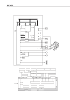
Power Supply Unit, 3.1 Power Supply Unit Block Diagram, Construction of Power Supply Unit
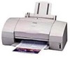 |
View all Canon BJC 6000 manuals
Add to My Manuals
Save this manual to your list of manuals |
Page 113 highlights
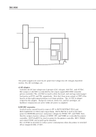
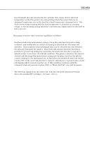
BJC-6000 4.3 Power Supply Unit 4.3.1 Power Supply Unit Block Diagram Part 4: Technical Reference AC100V +24V DC Carriage Motor (VM) Paper Feed Motor (VM) BJ Cartridge (HVH) HVCONT(+24VDC output control signal) AC Adapter DC/DC Converter EEPROM Printer Controller +5V DC Control ROM +3V RGV3/inRGV3) DRAM MPU +5V DC(RGM5/RGV5I) +5V DC Print Position Sensor (VSEN) Home Position Sensor (VSEN) Ink Sensor (VSEN) BJ Cartridge (HVDD) Parallel Interface (VIF) Figure 4-34 Power Supply Unit Block Diagram 4.3.2 Construction of Power Supply Unit The power supply unit converts AC power line voltage into DC voltages that drive motors, ICs, BJ cartridges, etc. a) AC adapter Converts the AC line voltage into 2 groups of DC voltages, +24 VDC, and +5 VDC. The output of +24 VDC is controlled by the output signal (HVCONT) from the printer controller. The +24 VDC is used to drive the head, and carriage motor/paper feed motor as HVH, and VM, respectively. Note that there is no output of HVH if the head is at the replacement position or at home position. The +5 VDC is always output by the adapter. Except for sensors, driver ICs, and BJ cartridges, all hardware components are active while AC power is supplied. b) DC/DC converter Located on the control board to convert +5V to RGV5/RGV5I(+5 VDC) and RGV3/inRGV3(+3.3 VDC) and output them. RGV5/RGV5I is used as the drive power for EEPROM and reset, and power voltages for HVDD, VIF, and VSEN. Note that the output of power voltages of HVDD, VIF, and VSEN are controlled by printer controller. RGV3/inRGV3 is used as power for the printer controller, MPU, DRAM, and control ROM, and as pull-up for switches. The +3.3VDC is intended to reduce power consumption when the printer is switched off as compared with +5 VDC. 4-41
-
 1
1 -
2
-
3
-
4
-
5
-
6
-
7
-
8
-
9
-
10
-
11
-
12
-
13
-
14
-
15
-
16
-
17
-
18
-
19
-
20
-
21
-
22
-
23
-
24
-
25
-
26
-
27
-
28
-
29
-
30
-
31
-
32
-
33
-
34
-
35
-
36
-
37
-
38
-
39
-
40
-
41
-
42
-
43
-
44
-
45
-
46
-
47
-
48
-
49
-
50
-
51
-
52
-
53
-
54
-
55
-
56
-
57
-
58
-
59
-
60
-
61
-
62
-
63
-
64
-
65
-
66
-
67
-
68
-
69
-
70
-
71
-
72
-
73
-
74
-
75
-
76
-
77
-
78
-
79
-
80
-
81
-
82
-
83
-
84
-
85
-
86
-
87
-
88
-
89
-
90
-
91
-
92
-
93
-
94
-
95
-
96
-
97
-
98
-
99
-
100
-
101
-
102
-
103
-
104
-
105
-
106
-
107
-
 108
108 -
 109
109 -
 110
110 -
 111
111 -
 112
112 -
 113
113 -
 114
114 -
 115
115 -
 116
116 -
 117
117 -
 118
118 -
119
-
120
-
121
-
122
-
123
-
124
-
125
-
126
-
127
-
128
-
129
-
130
-
131
-
132
-
133
-
134
-
135
-
136
-
137
-
138
-
139
-
140
-
141
-
142
-
143
-
144
-
145
-
146
-
147
-
148
-
149
-
150
-
151
-
152
-
153
-
154
-
155
-
156
-
157
-
158
-
159
-
160
-
161
-
162
-
163
-
164
-
165
-
166
-
167
-
168
-
169
-
170
-
171
-
172
-
173
-
174
 |
 |
