Canon BJC 6000 Service Manual - Page 114
DETECTION FUNCTIONS, Sensor Positions
 |
View all Canon BJC 6000 manuals
Add to My Manuals
Save this manual to your list of manuals |
Page 114 highlights
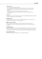
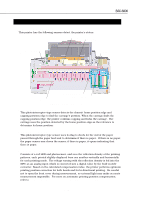
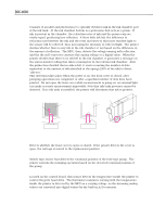
Part 4: Technical Reference 5. DETECTION FUNCTIONS 5.1 Detection with Sensors This printer has the following sensors detect the printer's status. Cover Sensor Paper End Sensor BJC-6000 Internal Temperature Sensor Pump Sensor Ink Sensor Print Position Sensor Home Position Sensor Figure 4-35 Sensor Positions 5.1.1 Home position sensor This photointerruptor-type sensor detects the chassis' home position edge and capping position edge to find the carriage's position. When the carriage finds the capping position edge, the printer confirms capping and locks the carriage. The carriage uses the position detected by the home position edge as the reference to determine its home position. 5.1.2 Paper end sensor This photointerruptor-type sensor uses its flag to check for the end of the paper passed through the paper feed unit to determine if there is paper. If there is no paper, the paper sensor arm closes the sensor; if there is paper, it opens indicating that there is paper. 5.1.3 Print position sensor Consists of a red LED and photosensor, and sees the reflection density of the printing patterns, each printed slightly displaced from one another vertically and horizontally for each printing mode. The voltage varying with the reflection density is fed into the MPU as an analog input which is converted into a digital value by the built-in A/D converter. Based on the calculated compensation value, the printer performs optimum printing position correction for both heads and for bi-directional printing. Be careful not to open the front cover during measurement, as external light may make accurate measurement impossible. For more on automatic printing position compensation, refer to Part 4: 2.3 Automatic Printing Position Alignment Function (page 4-15). 4-42
-
 1
1 -
2
-
3
-
4
-
5
-
6
-
7
-
8
-
9
-
10
-
11
-
12
-
13
-
14
-
15
-
16
-
17
-
18
-
19
-
20
-
21
-
22
-
23
-
24
-
25
-
26
-
27
-
28
-
29
-
30
-
31
-
32
-
33
-
34
-
35
-
36
-
37
-
38
-
39
-
40
-
41
-
42
-
43
-
44
-
45
-
46
-
47
-
48
-
49
-
50
-
51
-
52
-
53
-
54
-
55
-
56
-
57
-
58
-
59
-
60
-
61
-
62
-
63
-
64
-
65
-
66
-
67
-
68
-
69
-
70
-
71
-
72
-
73
-
74
-
75
-
76
-
77
-
78
-
79
-
80
-
81
-
82
-
83
-
84
-
85
-
86
-
87
-
88
-
89
-
90
-
91
-
92
-
93
-
94
-
95
-
96
-
97
-
98
-
99
-
100
-
101
-
102
-
103
-
104
-
105
-
106
-
107
-
108
-
 109
109 -
 110
110 -
 111
111 -
 112
112 -
 113
113 -
 114
114 -
 115
115 -
 116
116 -
 117
117 -
 118
118 -
 119
119 -
120
-
121
-
122
-
123
-
124
-
125
-
126
-
127
-
128
-
129
-
130
-
131
-
132
-
133
-
134
-
135
-
136
-
137
-
138
-
139
-
140
-
141
-
142
-
143
-
144
-
145
-
146
-
147
-
148
-
149
-
150
-
151
-
152
-
153
-
154
-
155
-
156
-
157
-
158
-
159
-
160
-
161
-
162
-
163
-
164
-
165
-
166
-
167
-
168
-
169
-
170
-
171
-
172
-
173
-
174
 |
 |
