Canon BJC 6000 Service Manual - Page 111
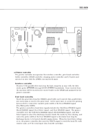
Buffer controller, DRAM controller, Stepping motor controller, Interrupt controller, I/O port
 |
View all Canon BJC 6000 manuals
Add to My Manuals
Save this manual to your list of manuals |
Page 111 highlights
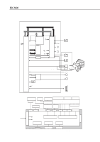
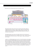
BJC-6000 Part 4: Technical Reference Buffer controller Writes the received data into the DRAM's receive buffer automatically, controls the remaining receive buffer capacity, reads the print buffer automatically, and clears the data that has been read. The print buffer manages two separate areas for the 2 heads. DRAM controller Performs control of the 16Mbit-DRAM's 16-bit data bus and 10-bit address bus, READ/WRITE control, RAS/CAS control, and REFRESH control, using the bus dedicated to DRAM which is separate from the MPU bus inside the printer controller. Stepping motor controller Transfers to the driver IC the steady current drive waveforms needed to drive motors. As the motor is sinuously driven, the data to be transferred to the IC is 16-bit/step drive waveform serial data that consists of motor drive current, motor torque setting, phase information, etc. Interrupt controller The printer controller has 4 interrupt pins on it. The interrupt controller generates parallel I/F, motor drive, and head drive interrupt requests to MPU(IC201). Also, it accepts an interrupt signal from the reset IC. I/O port Sends indicator lighting and the power supply voltage output control signals as output signals, receives sensor signals from the home position sensor, pump sensor, and paper end sensor as input signals, controls the EEPROM data I/O, and sends the motor driver reset signal as output. b) MPU (IC201) Incorporates a 32-bit CPU, 6Kbit work RAM, 21-bit address bus port, 16-bit data bus port, interrupt controller, A/D converter, and I/O port. The MPU selects the control ROM, printer controller, or DRAM according to the chip select signal. Built-in CPU 32-bit CPU operates in sync with the 20MHz external clock input. Address bus/Data bus The 21-bit address bus and 16-bit data bus operate in sync with the 20MHz external clock input. Interrupt controller Allows the MPU to receive the power on/off interrupt signal, as well as interrupt signals from the printer controller. 4-39
-
 1
1 -
2
-
3
-
4
-
5
-
6
-
7
-
8
-
9
-
10
-
11
-
12
-
13
-
14
-
15
-
16
-
17
-
18
-
19
-
20
-
21
-
22
-
23
-
24
-
25
-
26
-
27
-
28
-
29
-
30
-
31
-
32
-
33
-
34
-
35
-
36
-
37
-
38
-
39
-
40
-
41
-
42
-
43
-
44
-
45
-
46
-
47
-
48
-
49
-
50
-
51
-
52
-
53
-
54
-
55
-
56
-
57
-
58
-
59
-
60
-
61
-
62
-
63
-
64
-
65
-
66
-
67
-
68
-
69
-
70
-
71
-
72
-
73
-
74
-
75
-
76
-
77
-
78
-
79
-
80
-
81
-
82
-
83
-
84
-
85
-
86
-
87
-
88
-
89
-
90
-
91
-
92
-
93
-
94
-
95
-
96
-
97
-
98
-
99
-
100
-
101
-
102
-
103
-
104
-
105
-
 106
106 -
 107
107 -
 108
108 -
 109
109 -
 110
110 -
 111
111 -
 112
112 -
 113
113 -
 114
114 -
 115
115 -
 116
116 -
117
-
118
-
119
-
120
-
121
-
122
-
123
-
124
-
125
-
126
-
127
-
128
-
129
-
130
-
131
-
132
-
133
-
134
-
135
-
136
-
137
-
138
-
139
-
140
-
141
-
142
-
143
-
144
-
145
-
146
-
147
-
148
-
149
-
150
-
151
-
152
-
153
-
154
-
155
-
156
-
157
-
158
-
159
-
160
-
161
-
162
-
163
-
164
-
165
-
166
-
167
-
168
-
169
-
170
-
171
-
172
-
173
-
174
 |
 |