Canon BJC 6000 Service Manual - Page 93
Bubble Jet Nozzle part, 2.3 Construction of the bubble jet head unit
 |
View all Canon BJC 6000 manuals
Add to My Manuals
Save this manual to your list of manuals |
Page 93 highlights
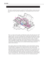
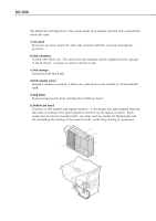
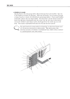
BJC-6000 Part 4: Technical Reference 3.2.3 Construction of the bubble jet head unit a) Bubble jet nozzle Ink absorbed in the ink sponge will be filtered through the mesh ink filter, then fed to the bubble jet nozzles via ink pipes. When the head drive current passes through a heater board in a nozzle, the ink will boil, producing bubbles. These small bubbles eventually coalesce into one large bubble. The head drive current will be turned off before the ink drop is discharged from the nozzle, but the after-heat of the heater causes the bubble to grow larger and be discharged from the nozzle tip as an ink drop. The nozzle is replenished with ink after the ink has been ejected. NOTE The print head uses semiconductor technology, in which the heaters and I/C circuits are mounted on a silicon plate. This silicon plate with electrical circuitry is bonded to an aluminum base which is then attached to a molded plastic cover with nozzles. Signal Circuit Print Circuit Board Ultra-thin Wire Connection Wire Connection Protective Bond Silicon Plate Aluminum Plate Heater Plate Bubble Jet Nozzle (1) Heater Driving Begins (2) Heater Is Driven Ink Channel Connected to Ink Sponge (3) Heater Driving Stops (4) Bubbles Contract to form an Ink Drop (5) Ink Drop Is Ejected Ink Filter Joint Pipe Plastic Cover Common Ink Chamber Face Plate (part of plastic cover) Figure 4-16 Bubble Jet Nozzle (part) 4-21
-
 1
1 -
2
-
3
-
4
-
5
-
6
-
7
-
8
-
9
-
10
-
11
-
12
-
13
-
14
-
15
-
16
-
17
-
18
-
19
-
20
-
21
-
22
-
23
-
24
-
25
-
26
-
27
-
28
-
29
-
30
-
31
-
32
-
33
-
34
-
35
-
36
-
37
-
38
-
39
-
40
-
41
-
42
-
43
-
44
-
45
-
46
-
47
-
48
-
49
-
50
-
51
-
52
-
53
-
54
-
55
-
56
-
57
-
58
-
59
-
60
-
61
-
62
-
63
-
64
-
65
-
66
-
67
-
68
-
69
-
70
-
71
-
72
-
73
-
74
-
75
-
76
-
77
-
78
-
79
-
80
-
81
-
82
-
83
-
84
-
85
-
86
-
87
-
 88
88 -
 89
89 -
 90
90 -
 91
91 -
 92
92 -
 93
93 -
 94
94 -
 95
95 -
 96
96 -
 97
97 -
 98
98 -
99
-
100
-
101
-
102
-
103
-
104
-
105
-
106
-
107
-
108
-
109
-
110
-
111
-
112
-
113
-
114
-
115
-
116
-
117
-
118
-
119
-
120
-
121
-
122
-
123
-
124
-
125
-
126
-
127
-
128
-
129
-
130
-
131
-
132
-
133
-
134
-
135
-
136
-
137
-
138
-
139
-
140
-
141
-
142
-
143
-
144
-
145
-
146
-
147
-
148
-
149
-
150
-
151
-
152
-
153
-
154
-
155
-
156
-
157
-
158
-
159
-
160
-
161
-
162
-
163
-
164
-
165
-
166
-
167
-
168
-
169
-
170
-
171
-
172
-
173
-
174
 |
 |