Canon BJC 6000 Service Manual - Page 98
Purge Unit, Construction of the purge unit
 |
View all Canon BJC 6000 manuals
Add to My Manuals
Save this manual to your list of manuals |
Page 98 highlights
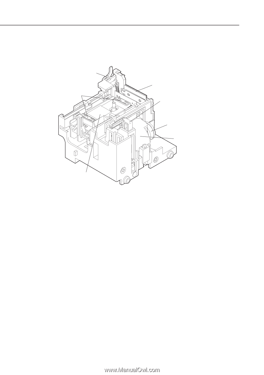
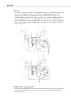
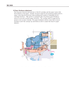
Part 4: Technical Reference 3.3.2 Construction of the purge unit BJC-6000 Wiper Release Unit Cap Unit Wiper Unit Carriage Lock Unit Purge Drive Gear Pump Unit Air Valve Unit Figure 4-20 Purge Unit a) Purge drive gear Receives the power of the feed roller driven by the paper feed motor via the drive switching unit to drive the pump. The pump roller's position is detected by the pump sensor. b) Wiper unit Operates when the carriage travels back and forth. It wipes off surplus ink from the head face plate as the carriage moves right to left at the completion of cleaning. It is constructed of two rubber wipers to enhance wiping performance,. c) Cap unit Uses the same rubber cap for both the capping action to protect the head, and for the pumping action to suck ink. There are two rubber caps, one per BJ cartridge installed on the carriage. Capping occurs by pressing the cap against the head's face plate when the carriage moves to the capping position. The rubber caps in the cap unit are connected to the pump unit and the air valve via the ink tube. During cleaning, the unit sucks ink from the head using the pump. The sucked ink will be sent to the waste ink absorber. After ink suction is completed, the carriage will be moved to the position that opens the air valve and pumping will be performed to suck out waste ink collected in the rubber cap. 4-26
-
 1
1 -
2
-
3
-
4
-
5
-
6
-
7
-
8
-
9
-
10
-
11
-
12
-
13
-
14
-
15
-
16
-
17
-
18
-
19
-
20
-
21
-
22
-
23
-
24
-
25
-
26
-
27
-
28
-
29
-
30
-
31
-
32
-
33
-
34
-
35
-
36
-
37
-
38
-
39
-
40
-
41
-
42
-
43
-
44
-
45
-
46
-
47
-
48
-
49
-
50
-
51
-
52
-
53
-
54
-
55
-
56
-
57
-
58
-
59
-
60
-
61
-
62
-
63
-
64
-
65
-
66
-
67
-
68
-
69
-
70
-
71
-
72
-
73
-
74
-
75
-
76
-
77
-
78
-
79
-
80
-
81
-
82
-
83
-
84
-
85
-
86
-
87
-
88
-
89
-
90
-
91
-
92
-
 93
93 -
 94
94 -
 95
95 -
 96
96 -
 97
97 -
 98
98 -
 99
99 -
 100
100 -
 101
101 -
 102
102 -
 103
103 -
104
-
105
-
106
-
107
-
108
-
109
-
110
-
111
-
112
-
113
-
114
-
115
-
116
-
117
-
118
-
119
-
120
-
121
-
122
-
123
-
124
-
125
-
126
-
127
-
128
-
129
-
130
-
131
-
132
-
133
-
134
-
135
-
136
-
137
-
138
-
139
-
140
-
141
-
142
-
143
-
144
-
145
-
146
-
147
-
148
-
149
-
150
-
151
-
152
-
153
-
154
-
155
-
156
-
157
-
158
-
159
-
160
-
161
-
162
-
163
-
164
-
165
-
166
-
167
-
168
-
169
-
170
-
171
-
172
-
173
-
174
 |
 |