Canon BJC 6000 Service Manual - Page 110
Logic Components, Control Board
 |
View all Canon BJC 6000 manuals
Add to My Manuals
Save this manual to your list of manuals |
Page 110 highlights
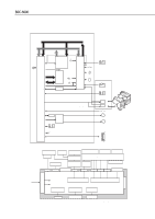
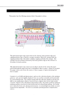
Part 4: Technical Reference 4.2.2 Logic Components CN401 RESUME Switch LED POWER Switch Cover Sensor ROM BJC-6000 CN603 CN402 CN602 CN404 CN403 Motor Driver Printer Controller Buzzer Paper End Sensor DRAM EEPROM MPU TH201 Figure 4-33 Control Board a) Printer controller The printer controller incorporates the interface controller, print head controller, buffer controller, DRAM controller, stepping motor controller and I/O ports and operates in sync with the 25MHz external clock input. Interface controller Receives 8-bit parallel data sent from the host computer in sync with the data strobe pulse (STROBE) through BUSY/ACKNLG handshake. Data received from the interface will be stored in the receive buffer in the DRAM and analyzed by the printer controller. Print head controller Reads the print data from the DRAM's print buffer and converts this parallel data into serial data to send to the print head. At the same time, it counts the printing dots needed to control the variable pulse width of the Heat ENABLE signal (Pre/Main pulse width). The printer controller's head drive signals include the Odd/Even ENABLE signal, Block ENABLE signal, Heat Select signal, and Heat ENABLE signal. The printer controller uses the Odd/Even ENABLE signal, Block ENABLE signal, and Heat Select signal to select the discharge heaters inside the nozzle by time sharing, and varies the pulse width of the Heat ENABLE signal to determine how long the discharge heater to be heated should remain driven. When the head drive voltage is on, the printer controller also uses the HDATA signal to send the head ID, rank resistor value as 6-bit serial input data from BJ cartridges. 4-38
-
 1
1 -
2
-
3
-
4
-
5
-
6
-
7
-
8
-
9
-
10
-
11
-
12
-
13
-
14
-
15
-
16
-
17
-
18
-
19
-
20
-
21
-
22
-
23
-
24
-
25
-
26
-
27
-
28
-
29
-
30
-
31
-
32
-
33
-
34
-
35
-
36
-
37
-
38
-
39
-
40
-
41
-
42
-
43
-
44
-
45
-
46
-
47
-
48
-
49
-
50
-
51
-
52
-
53
-
54
-
55
-
56
-
57
-
58
-
59
-
60
-
61
-
62
-
63
-
64
-
65
-
66
-
67
-
68
-
69
-
70
-
71
-
72
-
73
-
74
-
75
-
76
-
77
-
78
-
79
-
80
-
81
-
82
-
83
-
84
-
85
-
86
-
87
-
88
-
89
-
90
-
91
-
92
-
93
-
94
-
95
-
96
-
97
-
98
-
99
-
100
-
101
-
102
-
103
-
104
-
 105
105 -
 106
106 -
 107
107 -
 108
108 -
 109
109 -
 110
110 -
 111
111 -
 112
112 -
 113
113 -
 114
114 -
 115
115 -
116
-
117
-
118
-
119
-
120
-
121
-
122
-
123
-
124
-
125
-
126
-
127
-
128
-
129
-
130
-
131
-
132
-
133
-
134
-
135
-
136
-
137
-
138
-
139
-
140
-
141
-
142
-
143
-
144
-
145
-
146
-
147
-
148
-
149
-
150
-
151
-
152
-
153
-
154
-
155
-
156
-
157
-
158
-
159
-
160
-
161
-
162
-
163
-
164
-
165
-
166
-
167
-
168
-
169
-
170
-
171
-
172
-
173
-
174
 |
 |
