Canon BJC 6000 Service Manual - Page 109
Control Unit Block Diagram, Control Unit Function Diagram, Control Unit
 |
View all Canon BJC 6000 manuals
Add to My Manuals
Save this manual to your list of manuals |
Page 109 highlights
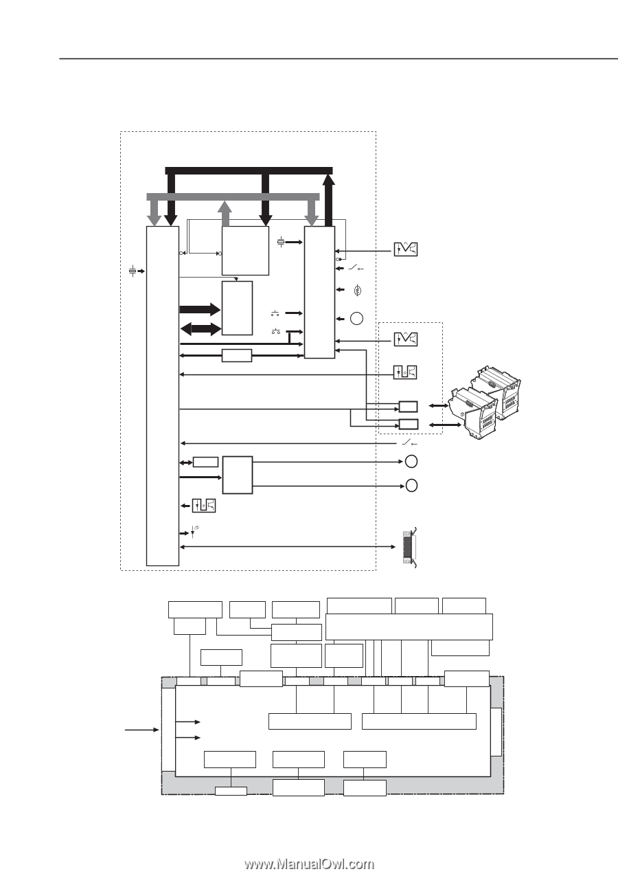
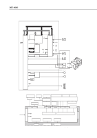
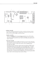
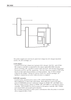
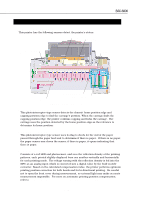
BJC-6000 4.2 Control Unit 4.2.1 Control unit block diagram Control Board Address Bus A1 - A21 Data Bus D0 - D15 Part 4: Technical Reference 0~15 AD1~21 D0~15 Control ROM A0~18 D0~15 A1~21 20MHz C51~53 CE 25MHz RAS,CAS DRAM Bus DRAM 16-Mbit MA0~9 MA 0~9 A0~9 MD MD0~15 0~15 I/O 1~16 Reset Switch INT 0~3 Power Switch RESX Reset IC PE0,2 PE4 Cover Sensor Ink Sensor MPU AN0 Internal Te m p e r a t u r e SensorTH201 P71 BZ Carriage Board P24 Buzzer IRQ AN6 0~4 RESX HRANK0,1 DIODE0,1 Print Position Sensor Printer Controller PC0 H_D0,1 H_CLOK0,1 HSEL1A0,1 H_RSTX ODD,EVEN HSEL1B0,1 H_LTH BENB0,1 HSEL2A0,1 HSEL2B0,1 DIR HENB0K*5 SUBH0,1 PC3 2 Kbit PB EEPROM 0~3 Driver IC PC1 Paper End Sensor PA1 Error Indicator Power Indicator Home Position Sensor BJ Cartridge Connector BJ Cartridge Connector Pump Sensor PM Carriage Motor PM Paper Feed Motor BJ Cartridges Parallel Interface Figure 4-31 Control Unit Block Diagram Purge Unit Purge Sensor ASF Unit Ink Sensor Paper Feed Roller Paper Feed Drive Switching Unit Paper Feed Motor Print Position Sensor BJ Cartridge BJ Cartridge Carriage motor Carriage Home Position Sensor CN602 CN603 Cover Sensor CN403 CN402 CN502 CN503 CN501 Paper End Sensor 100VAC +24V DC Motor Control Mechanical Control +5V DC Interface Control Indicator Control Switch Detection CN404 Indicator Operator Panel Buttons Control Unit Figure 4-32 Control Unit Function Diagram 4-37 AC Adapter Internal Temperature Sensor
-
 1
1 -
2
-
3
-
4
-
5
-
6
-
7
-
8
-
9
-
10
-
11
-
12
-
13
-
14
-
15
-
16
-
17
-
18
-
19
-
20
-
21
-
22
-
23
-
24
-
25
-
26
-
27
-
28
-
29
-
30
-
31
-
32
-
33
-
34
-
35
-
36
-
37
-
38
-
39
-
40
-
41
-
42
-
43
-
44
-
45
-
46
-
47
-
48
-
49
-
50
-
51
-
52
-
53
-
54
-
55
-
56
-
57
-
58
-
59
-
60
-
61
-
62
-
63
-
64
-
65
-
66
-
67
-
68
-
69
-
70
-
71
-
72
-
73
-
74
-
75
-
76
-
77
-
78
-
79
-
80
-
81
-
82
-
83
-
84
-
85
-
86
-
87
-
88
-
89
-
90
-
91
-
92
-
93
-
94
-
95
-
96
-
97
-
98
-
99
-
100
-
101
-
102
-
103
-
 104
104 -
 105
105 -
 106
106 -
 107
107 -
 108
108 -
 109
109 -
 110
110 -
 111
111 -
 112
112 -
 113
113 -
 114
114 -
115
-
116
-
117
-
118
-
119
-
120
-
121
-
122
-
123
-
124
-
125
-
126
-
127
-
128
-
129
-
130
-
131
-
132
-
133
-
134
-
135
-
136
-
137
-
138
-
139
-
140
-
141
-
142
-
143
-
144
-
145
-
146
-
147
-
148
-
149
-
150
-
151
-
152
-
153
-
154
-
155
-
156
-
157
-
158
-
159
-
160
-
161
-
162
-
163
-
164
-
165
-
166
-
167
-
168
-
169
-
170
-
171
-
172
-
173
-
174
 |
 |