Dell Latitude E5500 Service Manual - Page 10
Processor Module - fan
 |
View all Dell Latitude E5500 manuals
Add to My Manuals
Save this manual to your list of manuals |
Page 10 highlights
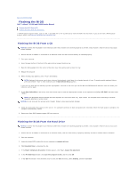
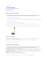
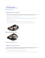
Back to Contents Page Processor Module Dell™ Latitude™ E5400 and E5500 Service Manual Removing the Processor Module Replacing the Processor Module Removing the Processor Module CAUTION: Before you begin the following procedure, follow the safety instructions that shipped with your computer. For additional safety best practices information, see the Regulatory Compliance Homepage on www.dell.com at: www.dell.com/regulatory_compliance. 1. Follow the instructions in Before Working on Your Computer. 2. Remove the bottom of the base assembly (see Removing the E5400 Bottom of the Base Assembly or Replacing the E5400 Bottom of the Base Assembly). 3. Remove the fan (see Removing the Fan). 4. Remove the processor heat sink (see Removing the Processor Heat Sink). NOTICE: To avoid damage to the processor, hold the screwdriver so that it is perpendicular to the processor when turning the cam screw. 5. To loosen the ZIF socket, use a small, flat-blade screwdriver and rotate the ZIF-socket cam screw counterclockwise until it comes to the cam stop. 1 ZIF-socket cam screw 2 ZIF socket NOTICE: To ensure maximum cooling for the processor, do not touch the heat transfer areas on the processor heat sink. The oils in your skin can reduce the heat transfer capability of the thermal pads. NOTICE: When removing the processor module, pull the module straight up. Be careful not to bend the pins on the processor module. 6. Lift the processor module from the ZIF socket. Replacing the Processor Module CAUTION: Before you begin the following procedure, follow the safety instructions that shipped with your computer. For additional safety best practices information, see the Regulatory Compliance Homepage on www.dell.com at: www.dell.com/regulatory_compliance. NOTICE: Do not touch the processor die. Press and hold the processor down on the substrate on which the die is mounted while turning the cam screw to prevent intermittent contact between the cam screw and processor. NOTICE: Ensure that the cam lock is in the fully open position before seating the processor module. Seating the processor module properly in the ZIF socket does not require force. A processor module that is not properly seated can result in an intermittent connection or permanent damage to the microprocessor and ZIF socket. NOTE: If you are installing a new processor, you receive a new processor heat sink, which will include an affixed thermal pad, or you will receive a new thermal pad along with a tech sheet to illustrate proper installation. NOTE: This procedure assumes that you have completed the removal procedure first. 1. Align the pin-1 corner of the processor module with the pin-1 corner of the ZIF socket, then insert the processor module.
-
 1
1 -
2
-
3
-
4
-
 5
5 -
 6
6 -
 7
7 -
 8
8 -
 9
9 -
 10
10 -
 11
11 -
 12
12 -
 13
13 -
 14
14 -
 15
15 -
16
-
17
-
18
-
19
-
20
-
21
-
22
-
23
-
24
-
25
-
26
-
27
-
28
-
29
-
30
-
31
-
32
-
33
-
34
-
35
-
36
-
37
-
38
-
39
-
40
-
41
-
42
-
43
-
44
-
45
-
46
-
47
-
48
-
49
-
50
-
51
-
52
-
53
-
54
-
55
-
56
-
57
-
58
-
59
-
60
-
61
-
62
-
63
-
64
-
65
-
66
-
67
-
68
-
69
-
70
-
71
-
72
-
73
 |
 |