Dell Latitude E5500 Service Manual - Page 11
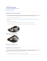
Replacing the E5500 Bottom of the Base Assembly - processor
 |
View all Dell Latitude E5500 manuals
Add to My Manuals
Save this manual to your list of manuals |
Page 11 highlights
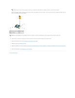
NOTE: The pin-1 corner of the processor module has a triangle that aligns with the triangle on the pin-1 corner of the ZIF socket. When the processor module is properly seated, all four corners are aligned at the same height. If one or more corners of the module are higher than the others, the module is not seated properly. 1 ZIF-socket cam screw 2 ZIF socket 3 pin-1 corner NOTICE: To avoid damage to the processor, hold the screwdriver so that it is perpendicular to the processor when turning the cam screw. 2. Tighten the ZIF socket by turning the cam screw clockwise to secure the processor module to the system board. 3. Replace the processor heat sink (see Replacing the Processor Heat Sink). 4. Replace the fan (see Replacing the Fan). 5. Replace the bottom of the base assembly (see Replacing the E5400 Bottom of the Base Assembly or Replacing the E5500 Bottom of the Base Assembly). 6. Follow the procedures in After Working on Your Computer. Back to Contents Page
-
 1
1 -
2
-
3
-
4
-
5
-
 6
6 -
 7
7 -
 8
8 -
 9
9 -
 10
10 -
 11
11 -
 12
12 -
 13
13 -
 14
14 -
 15
15 -
 16
16 -
17
-
18
-
19
-
20
-
21
-
22
-
23
-
24
-
25
-
26
-
27
-
28
-
29
-
30
-
31
-
32
-
33
-
34
-
35
-
36
-
37
-
38
-
39
-
40
-
41
-
42
-
43
-
44
-
45
-
46
-
47
-
48
-
49
-
50
-
51
-
52
-
53
-
54
-
55
-
56
-
57
-
58
-
59
-
60
-
61
-
62
-
63
-
64
-
65
-
66
-
67
-
68
-
69
-
70
-
71
-
72
-
73
 |
 |
