Dell Latitude E5500 Service Manual - Page 18
E5400 Display Inverter
 |
View all Dell Latitude E5500 manuals
Add to My Manuals
Save this manual to your list of manuals |
Page 18 highlights
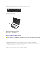
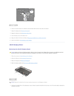
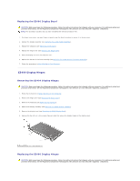
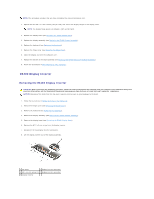
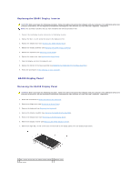
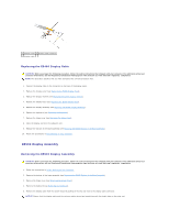
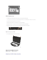
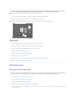
NOTE: This procedure assumes that you have completed the removal procedure first. 1. Replace the four M2.5 x 5-mm screws (two per side) that secure the display hinges to the display cover. NOTE: The display hinge panels are labeled L (left) and R (right). 2. Replace the display bezel (see Replacing the E5500 Display Bezel). 3. Replace the display assembly (see Replacing the E5400 Display Assembly). 4. Replace the keyboard (see Replacing the Keyboard). 5. Replace the hinge cover (see Replacing the Hinge Cover). 6. Close the display and turn the computer over. 7. Replace the bottom of the base assembly (see Replacing the E5400 Bottom of the Base Assembly). 8. Follow the procedures in After Working on Your Computer. E5400 Display Inverter Removing the E5400 Display Inverter CAUTION: Before you begin the following procedure, follow the safety instructions that shipped with your computer. For additional safety best practices information, see the Regulatory Compliance Homepage on www.dell.com at: www.dell.com/regulatory_compliance. NOTICE: Removal of the bezel from the top cover requires extreme care to avoid damage to the bezel. 1. Follow the instructions in Before Working on Your Computer. 2. Remove the hinge cover (see Removing the Hinge Cover). 3. Remove the keyboard (see Removing the Keyboard). 4. Remove the display assembly (see Removing the E5400 Display Assembly). 5. Remove the display bezel (see Removing the E5400 Display Bezel). 6. Remove the M2.5 x 5-mm screw from the display inverter. 7. Disconnect the two display inverter connectors. 8. Lift the display inverter out of the display assembly. 1 top cover 2 display inverter connector 3 M2.5 x 5-mm screw (1) 4 display inverter connector 5 display inverter
-
 1
1 -
2
-
3
-
4
-
5
-
6
-
7
-
8
-
9
-
10
-
11
-
12
-
 13
13 -
 14
14 -
 15
15 -
 16
16 -
 17
17 -
 18
18 -
 19
19 -
 20
20 -
 21
21 -
 22
22 -
 23
23 -
24
-
25
-
26
-
27
-
28
-
29
-
30
-
31
-
32
-
33
-
34
-
35
-
36
-
37
-
38
-
39
-
40
-
41
-
42
-
43
-
44
-
45
-
46
-
47
-
48
-
49
-
50
-
51
-
52
-
53
-
54
-
55
-
56
-
57
-
58
-
59
-
60
-
61
-
62
-
63
-
64
-
65
-
66
-
67
-
68
-
69
-
70
-
71
-
72
-
73
 |
 |