Dell Latitude E5500 Service Manual - Page 3
Removing the E5500 Bottom of the Base Assembly, Replacing the E5500 Bottom of the Base Assembly
 |
View all Dell Latitude E5500 manuals
Add to My Manuals
Save this manual to your list of manuals |
Page 3 highlights
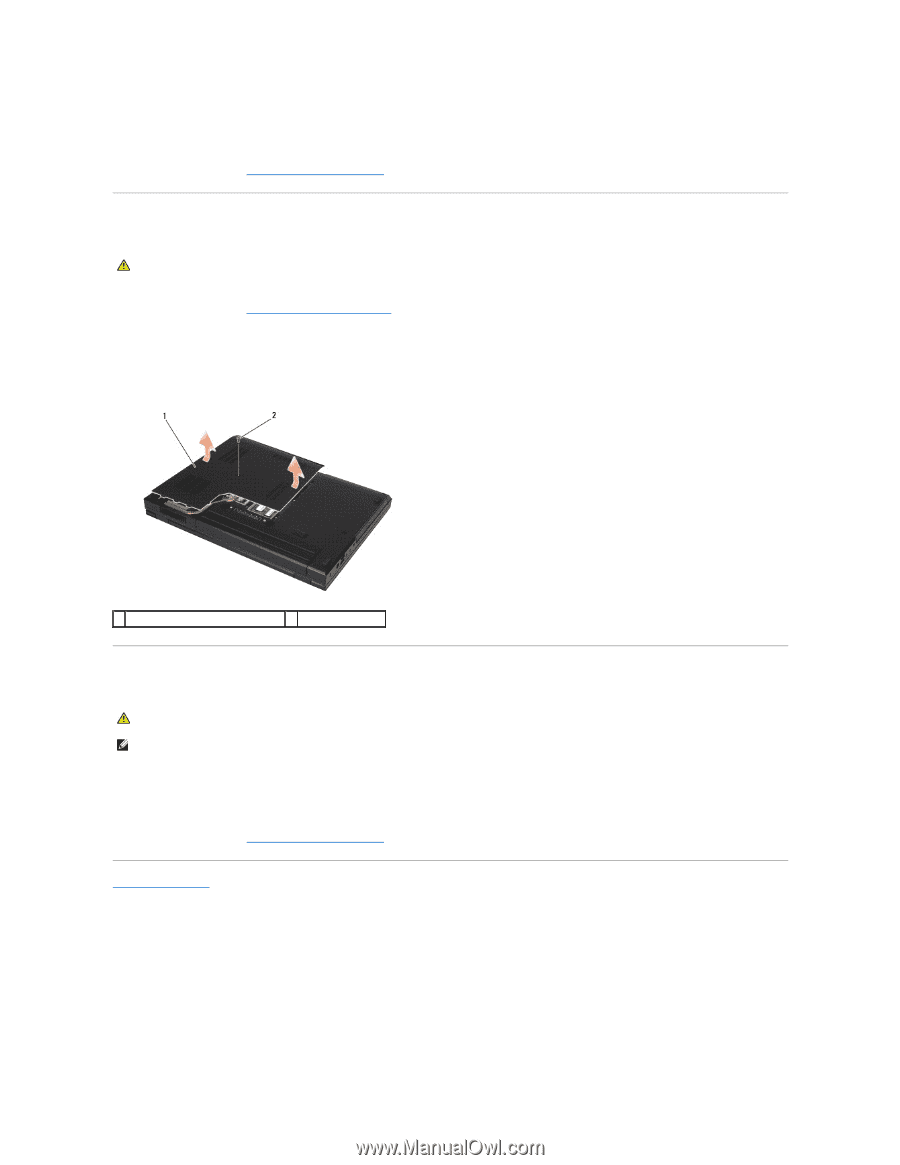
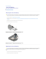
1. Slide in the bottom of the base assembly to the left of the computer, hold it down, and snap it into place. 2. Tighten the captive screws, making sure the bottom of the base assembly is snapped down. 3. Follow the procedures in After Working on Your Computer. Removing the E5500 Bottom of the Base Assembly CAUTION: Before you begin any of the procedures in this section, follow the safety instructions that shipped with your computer. For additional safety best practices information, see the Regulatory Compliance Homepage on www.dell.com at: www.dell.com/regulatory_compliance. 1. Follow the procedures in Before Working on Your Computer. 2. Close the display and turn the computer upside down. 3. Remove the single M2.5 x 8-mm screw securing the bottom of the base assembly. 4. Slide the bottom of the base assembly toward the front of the computer, and lift it up. 1 E5500 bottom of the base assembly 2 M2.5 x 8-mm screw Replacing the E5500 Bottom of the Base Assembly CAUTION: Before you begin any of the procedures in this section, follow the safety instructions that shipped with your computer. For additional safety best practices information, see the Regulatory Compliance Homepage on www.dell.com at: www.dell.com/regulatory_compliance. NOTE: This procedure assumes that you have completed the removal procedure first. 1. Slide the bottom of the base assembly toward the back of the computer until it is fully seated. 2. Replace the single M2.5 x 8-mm screw securing the bottom of the base assembly. 3. Follow the procedures in After Working on Your Computer. Back to Contents Page
-
 1
1 -
 2
2 -
 3
3 -
 4
4 -
 5
5 -
 6
6 -
 7
7 -
 8
8 -
 9
9 -
10
-
11
-
12
-
13
-
14
-
15
-
16
-
17
-
18
-
19
-
20
-
21
-
22
-
23
-
24
-
25
-
26
-
27
-
28
-
29
-
30
-
31
-
32
-
33
-
34
-
35
-
36
-
37
-
38
-
39
-
40
-
41
-
42
-
43
-
44
-
45
-
46
-
47
-
48
-
49
-
50
-
51
-
52
-
53
-
54
-
55
-
56
-
57
-
58
-
59
-
60
-
61
-
62
-
63
-
64
-
65
-
66
-
67
-
68
-
69
-
70
-
71
-
72
-
73
 |
 |