Dell Latitude E5500 Service Manual - Page 73
realign the card.
 |
View all Dell Latitude E5500 manuals
Add to My Manuals
Save this manual to your list of manuals |
Page 73 highlights
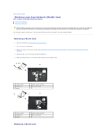
NOTICE: The connectors are keyed to ensure correct insertion. If you feel resistance, check the connectors on the card and on the system board, and realign the card. NOTICE: To avoid damage to the WLAN card, never place cables under the card. NOTE: This procedure assumes that you have completed the removal procedure first. 1. Insert the WLAN card connector into the system board connector at a 45-degree angle. 2. Press the card flat and replace the M2 x 3-mm screw that secures the WLAN card. 3. Replace the bottom of the base assembly (see Replacing the E5400 Bottom of the Base Assembly or Replacing the E5500 Bottom of the Base Assembly). 4. Follow the procedures in After Working on Your Computer. Back to Contents Page
-
 1
1 -
2
-
3
-
4
-
5
-
6
-
7
-
8
-
9
-
10
-
11
-
12
-
13
-
14
-
15
-
16
-
17
-
18
-
19
-
20
-
21
-
22
-
23
-
24
-
25
-
26
-
27
-
28
-
29
-
30
-
31
-
32
-
33
-
34
-
35
-
36
-
37
-
38
-
39
-
40
-
41
-
42
-
43
-
44
-
45
-
46
-
47
-
48
-
49
-
50
-
51
-
52
-
53
-
54
-
55
-
56
-
57
-
58
-
59
-
60
-
61
-
62
-
63
-
64
-
65
-
66
-
67
-
 68
68 -
 69
69 -
 70
70 -
 71
71 -
 72
72 -
 73
73
 |
 |

1.
Insert the WLAN card connector into the system board connector at a 45-degree angle.
2.
Press the card flat and replace the M2 x 3-mm screw that secures the WLAN card.
3.
Replace the bottom of the base assembly (see
Replacing the E5400 Bottom of the Base Assembly
or
Replacing the E5500 Bottom of the Base Assembly
).
4.
Follow the procedures in
After Working on Your Computer
.
Back to Contents Page
NOTICE:
The connectors are keyed to ensure correct insertion. If you feel resistance, check the connectors on the card and on the system board, and
realign the card.
NOTICE:
To avoid damage to the WLAN card, never place cables under the card.
NOTE:
This procedure assumes that you have completed the removal procedure first.