Dell Latitude E5500 Service Manual - Page 59
Replacing the E5500 System Board Assembly
 |
View all Dell Latitude E5500 manuals
Add to My Manuals
Save this manual to your list of manuals |
Page 59 highlights
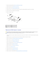
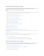
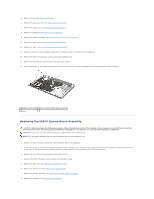
5. Remove the fan (see Removing the Fan). 6. Remove the processor heat sink (see Processor Heat Sink). 7. Remove the hinge cover (see Removing the Hinge Cover). 8. Remove the keyboard (see Removing the Keyboard). 9. Remove the display assembly (see Removing the E5500 Display Assembly). 10. Remove the optical drive (see Removing the Optical Drive). 11. Remove the palm rest (see Removing the E5500 Palm Rest). 12. Carefully remove the coin cell battery cable from the system board on the bottom of the computer. 13. Remove the serial I/O connector to the system board (E5500 only). 14. Remove the three M2.5 x 5-mm screws from the system board. 15. Lift the right edge of the system board off of the I/O board connector, and then carefully lift the system board out of the computer. 1 E5500 system board 2 M2.5 x 5-mm system board screws (3) 3 base Replacing the E5500 System Board Assembly CAUTION: Before you begin the following procedure, follow the safety instructions that shipped with your computer. For additional safety best practices information, see the Regulatory Compliance Homepage on www.dell.com at: www.dell.com/regulatory_compliance. NOTICE: Ensure that any loose cables do not get caught beneath the system board. NOTE: This procedure assumes that you have completed the removal procedure first. 1. Connect the coin cell battery connector from the bottom side of the computer. 2. Insert the left side of the system board into the base of the computer at an angle until the connectors on the system board are aligned with the holes on the base of the computer, then carefully lower the system board into place and into the I/O board connector. 3. Replace the three M2.5 x 5-mm screws on the system board. 4. Connect the serial I/O cable to the connector on the system board. 5. Replace the palm rest (see Replacing the E5500 Palm Rest). 6. Replace the optical drive (see Replacing the Optical Drive). 7. Replace the display assembly (see Replacing the E5500 Display Assembly). 8. Replace the keyboard (see Replacing the Keyboard).
-
 1
1 -
2
-
3
-
4
-
5
-
6
-
7
-
8
-
9
-
10
-
11
-
12
-
13
-
14
-
15
-
16
-
17
-
18
-
19
-
20
-
21
-
22
-
23
-
24
-
25
-
26
-
27
-
28
-
29
-
30
-
31
-
32
-
33
-
34
-
35
-
36
-
37
-
38
-
39
-
40
-
41
-
42
-
43
-
44
-
45
-
46
-
47
-
48
-
49
-
50
-
51
-
52
-
53
-
 54
54 -
 55
55 -
 56
56 -
 57
57 -
 58
58 -
 59
59 -
 60
60 -
 61
61 -
 62
62 -
 63
63 -
 64
64 -
65
-
66
-
67
-
68
-
69
-
70
-
71
-
72
-
73
 |
 |