Dell Latitude E5500 Service Manual - Page 50
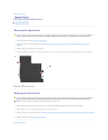
Removing the E5500 Palm Rest
 |
View all Dell Latitude E5500 manuals
Add to My Manuals
Save this manual to your list of manuals |
Page 50 highlights
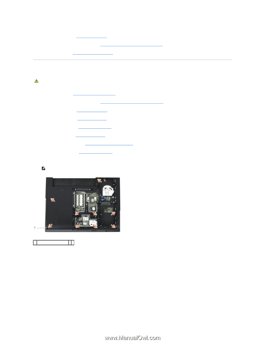
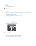
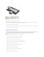
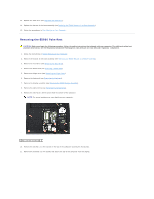
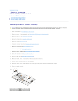
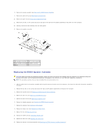
13. Replace the hard drive (see Replacing the Hard Drive). 14. Replace the bottom of the base assembly (see Replacing the E5400 Bottom of the Base Assembly). 15. Follow the procedures in After Working on Your Computer. Removing the E5500 Palm Rest CAUTION: Before you begin the following procedure, follow the safety instructions that shipped with your computer. For additional safety best practices information, see the Regulatory Compliance Homepage on www.dell.com at: www.dell.com/regulatory_compliance. 1. Follow the instructions in Before Working on Your Computer. 2. Remove the bottom of the base assembly (see Removing the E5400 Bottom of the Base Assembly). 3. Remove the hard drive (see Removing the Hard Drive). 4. Remove the WLAN card (see Removing a WLAN Card). 5. Remove the hinge cover (see Removing the Hinge Cover). 6. Remove the keyboard (see Removing the Keyboard). 7. Remove the display assembly (see Removing the E5500 Display Assembly). 8. Remove the optical drive (see Removing the Optical Drive). 9. Remove the nine M2.5 x 8-mm screws from the bottom of the computer. NOTE: The screw locations may vary slightly on your computer. 1 M2.5 x 8-mm screws (9) 10. Remove the two M2.5 x 5-mm screws on the top of the computer securing the metal plate. 11. Remove the three M2 x 3-mm screws that secure the top of the computer near the display.
-
 1
1 -
2
-
3
-
4
-
5
-
6
-
7
-
8
-
9
-
10
-
11
-
12
-
13
-
14
-
15
-
16
-
17
-
18
-
19
-
20
-
21
-
22
-
23
-
24
-
25
-
26
-
27
-
28
-
29
-
30
-
31
-
32
-
33
-
34
-
35
-
36
-
37
-
38
-
39
-
40
-
41
-
42
-
43
-
44
-
 45
45 -
 46
46 -
 47
47 -
 48
48 -
 49
49 -
 50
50 -
 51
51 -
 52
52 -
 53
53 -
 54
54 -
 55
55 -
56
-
57
-
58
-
59
-
60
-
61
-
62
-
63
-
64
-
65
-
66
-
67
-
68
-
69
-
70
-
71
-
72
-
73
 |
 |