Dell OptiPlex 320 User Guide - Page 108
Drives, Connectors, Key Combinations, Windows, Security, Controls and Lights - amber light
 |
UPC - 683728237738
View all Dell OptiPlex 320 manuals
Add to My Manuals
Save this manual to your list of manuals |
Page 108 highlights
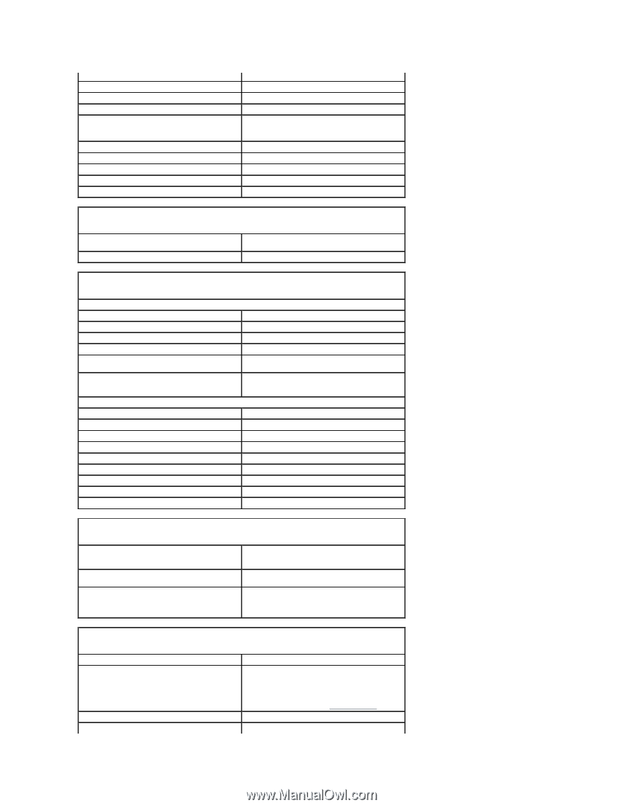
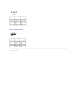
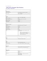
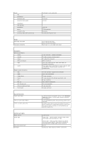
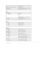
Cards: PCI: connectors connector size connector data width (maximum) PCI Express: connectors power connector size connector data width (maximum) Drives Externally accessible Internally accessible Connectors External connectors: Serial Parallel Video Network adapter USB Audio System board connectors: IDE SATA Floppy drive Serial Fan PCI 2.3 PCI Express x16 CD drive audio interface Front panel Key Combinations or or Controls and Lights Power control Power light Hard-drive access light Link light full-height cards supported two 120 pins 32 bits one x16 25 W maximum 164 pins sixteen PCI Express lane one 3.5-inch drive bay two 5.25-inch drive bays two bays for 1-inch-high hard drives 9-pin connector; 16550C-compatible 25-hole connector (bidirectional) 15-hole VGA connector RJ-45 connector two front-panel and four back-panel USB 2.0- compliant connectors three back-panel connectors for line-in, line-out, and microphone; one front-panel connector for headphones 40-pin connector (supports two devices) four 7-pin connectors 34-pin connector 12-pin connector for optional serial port card 5-pin connector two 120-pin connectors 164-pin connector 4-pin connector 40-pin connector in Microsoft® Windows® XP, brings up the Windows Security window.; in DOS mode, restarts (reboots) the computer starts embedded system setup (during system startup only) displays a boot device menu that allows the user to enter a device for a single boot (during system startup only) as well as options to run hard-drive and system diagnostics push button green light - Blinking green indicates sleep mode; solid green indicates power-on state. amber light - Blinking amber indicates a problem with an installed device; solid amber indicates an internal power problem (see Power Problems). green solid green light indicates network connection
-
 1
1 -
2
-
3
-
4
-
5
-
6
-
7
-
8
-
9
-
10
-
11
-
12
-
13
-
14
-
15
-
16
-
17
-
18
-
19
-
20
-
21
-
22
-
23
-
24
-
25
-
26
-
27
-
28
-
29
-
30
-
31
-
32
-
33
-
34
-
35
-
36
-
37
-
38
-
39
-
40
-
41
-
42
-
43
-
44
-
45
-
46
-
47
-
48
-
49
-
50
-
51
-
52
-
53
-
54
-
55
-
56
-
57
-
58
-
59
-
60
-
61
-
62
-
63
-
64
-
65
-
66
-
67
-
68
-
69
-
70
-
71
-
72
-
73
-
74
-
75
-
76
-
77
-
78
-
79
-
80
-
81
-
82
-
83
-
84
-
85
-
86
-
87
-
88
-
89
-
90
-
91
-
92
-
93
-
94
-
95
-
96
-
97
-
98
-
99
-
100
-
101
-
102
-
 103
103 -
 104
104 -
 105
105 -
 106
106 -
 107
107 -
 108
108 -
 109
109 -
 110
110 -
 111
111 -
 112
112 -
 113
113 -
114
-
115
-
116
-
117
-
118
-
119
-
120
-
121
-
122
-
123
-
124
-
125
-
126
-
127
-
128
-
129
-
130
-
131
-
132
-
133
-
134
-
135
-
136
-
137
-
138
-
139
-
140
 |
 |