Dell OptiPlex 320 User Guide - Page 78
Product Information Guide - sound
 |
UPC - 683728237738
View all Dell OptiPlex 320 manuals
Add to My Manuals
Save this manual to your list of manuals |
Page 78 highlights
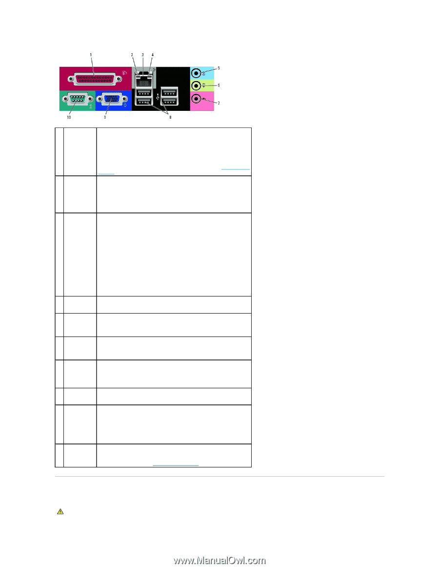
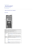
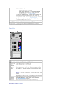
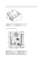
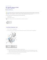
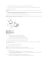
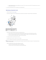
1 parallel connector Connect a parallel device, such as a printer, to the parallel connector. If you have a USB printer, plug it into a USB connector. 2 link integrity light NOTE: The integrated parallel connector is automatically disabled if the computer detects an installed card containing a parallel connector configured to the same address. For more information, see System Setup Options. l Green - A good connection exists between a 10-Mbps network and the computer. l Orange - A good connection exists between a 100-Mbps network and the computer. l Off - The computer is not detecting a physical connection to the network. 3 network adapter connector To attach your computer to a network or broadband device, connect one end of a network cable to either a network jack or your network or broadband device. Connect the other end of the network cable to the network adapter connector on the back panel of your computer. A click indicates that the network cable has been securely attached. NOTE: Do not plug a telephone cable into the network connector. On computers with a network adapter card, use the connector on the card. 4 network activity light 5 line-in connector It is recommended that you use Category 5 wiring and connectors for your network. If you must use Category 3 wiring, force the network speed to 10 Mbps to ensure reliable operation. This light flashes yellow when the computer is transmitting or receiving network data. A high volume of network traffic may make this light appear to be in a steady "on" state. Use the blue line-in connector to attach a record/playback device such as a cassette player, CD player, or VCR. 6 line-out connector On computers with a sound card, use the connector on the card. Use the green line-out connector to attach headphones and most speakers with integrated amplifiers. 7 microphone connector On computers with a sound card, use the connector on the card. Use the pink microphone connector to attach a personal computer microphone for voice or musical input into a sound or telephony program. 8 USB 2.0 connectors (4) 9 video connector On computers with a sound card, the microphone connector is on the card. Use the back USB connectors for devices that typically remain connected, such as printers and keyboards. Plug the cable from your VGA-compatible monitor into the blue connector. 10 serial connector NOTE: If you purchased an optional graphics card, this connector will be covered by a cap. Connect your monitor to the connector on the graphics card. Do not remove the cap. Connect a serial device, such as a handheld device, to the serial port. The default designation is COM1 for serial connector 1. For more information, see System Setup Options. Inside Your Computer CAUTION: Before you begin any of the procedures in this section, follow the safety instructions located in the Product Information Guide.
-
 1
1 -
2
-
3
-
4
-
5
-
6
-
7
-
8
-
9
-
10
-
11
-
12
-
13
-
14
-
15
-
16
-
17
-
18
-
19
-
20
-
21
-
22
-
23
-
24
-
25
-
26
-
27
-
28
-
29
-
30
-
31
-
32
-
33
-
34
-
35
-
36
-
37
-
38
-
39
-
40
-
41
-
42
-
43
-
44
-
45
-
46
-
47
-
48
-
49
-
50
-
51
-
52
-
53
-
54
-
55
-
56
-
57
-
58
-
59
-
60
-
61
-
62
-
63
-
64
-
65
-
66
-
67
-
68
-
69
-
70
-
71
-
72
-
 73
73 -
 74
74 -
 75
75 -
 76
76 -
 77
77 -
 78
78 -
 79
79 -
 80
80 -
 81
81 -
 82
82 -
 83
83 -
84
-
85
-
86
-
87
-
88
-
89
-
90
-
91
-
92
-
93
-
94
-
95
-
96
-
97
-
98
-
99
-
100
-
101
-
102
-
103
-
104
-
105
-
106
-
107
-
108
-
109
-
110
-
111
-
112
-
113
-
114
-
115
-
116
-
117
-
118
-
119
-
120
-
121
-
122
-
123
-
124
-
125
-
126
-
127
-
128
-
129
-
130
-
131
-
132
-
133
-
134
-
135
-
136
-
137
-
138
-
139
-
140
 |
 |