Dell OptiPlex 320 User Guide - Page 41
DC Power Connectors
 |
UPC - 683728237738
View all Dell OptiPlex 320 manuals
Add to My Manuals
Save this manual to your list of manuals |
Page 41 highlights
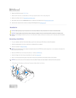
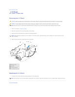
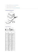
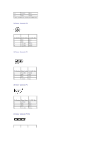
11. Replace the CD/DVD drive (see Installing a CD/DVD Drive). 12. Connect the AC power cable to the connector. 13. Replace the computer cover (see Replacing the Computer Cover). DC Power Connectors DC Power Connector P1 Pin Number Signal name 18-AWG Wire 1 +3.3 VDC Orange 2 +3.3 VDC Orange 3 GND Black 4 +5 VDC Red 5 GND Black 6 +5 VDC Red 7 GND Black 8 PS_PWROK* Gray 9 P5AUX Purple 10 +12 VDC White 11 +12 VDC White 12 +3.3 VDC Orange 13 +3.3 VDC Orange 14 -12 VDC* Blue 15 GND Black 16 PWR_PS_ON* Green 17 GND Black 18 GND Black 19 GND Black 20 NC N/C 21 +5 VDC Red 22 +5 VDC Red
-
 1
1 -
2
-
3
-
4
-
5
-
6
-
7
-
8
-
9
-
10
-
11
-
12
-
13
-
14
-
15
-
16
-
17
-
18
-
19
-
20
-
21
-
22
-
23
-
24
-
25
-
26
-
27
-
28
-
29
-
30
-
31
-
32
-
33
-
34
-
35
-
 36
36 -
 37
37 -
 38
38 -
 39
39 -
 40
40 -
 41
41 -
 42
42 -
 43
43 -
 44
44 -
 45
45 -
 46
46 -
47
-
48
-
49
-
50
-
51
-
52
-
53
-
54
-
55
-
56
-
57
-
58
-
59
-
60
-
61
-
62
-
63
-
64
-
65
-
66
-
67
-
68
-
69
-
70
-
71
-
72
-
73
-
74
-
75
-
76
-
77
-
78
-
79
-
80
-
81
-
82
-
83
-
84
-
85
-
86
-
87
-
88
-
89
-
90
-
91
-
92
-
93
-
94
-
95
-
96
-
97
-
98
-
99
-
100
-
101
-
102
-
103
-
104
-
105
-
106
-
107
-
108
-
109
-
110
-
111
-
112
-
113
-
114
-
115
-
116
-
117
-
118
-
119
-
120
-
121
-
122
-
123
-
124
-
125
-
126
-
127
-
128
-
129
-
130
-
131
-
132
-
133
-
134
-
135
-
136
-
137
-
138
-
139
-
140
 |
 |
11.
Replace the CD/DVD drive (see
Installing a CD/DVD Drive
).
12.
Connect the AC power cable to the connector.
13.
Replace the computer cover (see
Replacing the Computer Cover
).
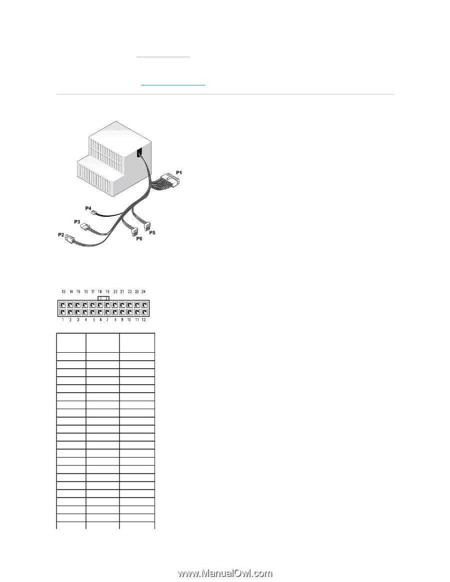
DC Power Connectors
DC Power Connector P1
Pin Number
Signal name
18-AWG Wire
1
+3.3 VDC
Orange
2
+3.3 VDC
Orange
3
GND
Black
4
+5 VDC
Red
5
GND
Black
6
+5 VDC
Red
7
GND
Black
8
PS_PWROK*
Gray
9
P5AUX
Purple
10
+12 VDC
White
11
+12 VDC
White
12
+3.3 VDC
Orange
13
+3.3 VDC
Orange
14
-12 VDC*
Blue
15
GND
Black
16
PWR_PS_ON*
Green
17
GND
Black
18
GND
Black
19
GND
Black
20
NC
N/C
21
+5 VDC
Red
22
+5 VDC
Red