Dell OptiPlex 320 User Guide - Page 77
Power Problems, Power Management, System Lights, Panel Connectors - power switch
 |
UPC - 683728237738
View all Dell OptiPlex 320 manuals
Add to My Manuals
Save this manual to your list of manuals |
Page 77 highlights
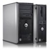
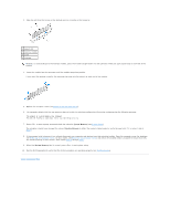
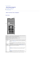
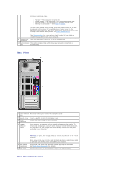
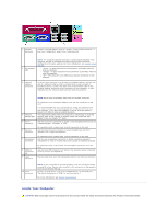
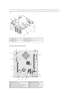
different operating states: l No light - The computer is turned off. l Steady green - The computer is in a normal operating state. l Blinking green - The computer is in a power-saving mode. l Blinking or solid amber - See Power Problems. To exit from a power-saving mode, press the power button or use the keyboard or the mouse if it is configured as a wake device in the Windows Device Manager. For more information about sleep modes and exiting from a power-saving mode, see Power Management. See System Lights for a description of light codes that can help you troubleshoot problems with your computer. 9 headphone connector Use the headphone connector to attach headphones. 10 LAN indicator This light indicates that a LAN (local area network) connection is light established. Back View 1 cover release This latch allows you to open the computer cover. latch 2 padlock ring Insert a padlock to lock the computer cover. 3 power connector Insert the power cable into this connector. 4 voltage selection switch Your computer is equipped with a manual voltage-selection switch. To help avoid damaging a computer with a manual voltage-selection switch, set the switch for the voltage that most closely matches the AC power available in your location. 5 back-panel connectors 6 card slots NOTICE: In Japan, the voltage selection switch must be set to the 115-V position. Also, ensure that your monitor and attached devices are electrically rated to operate with the AC power available in your location. Plug serial, USB, and other devices into the appropriate connector. See Back-Panel Connectors for details. Access connectors for any installed PCI and PCI Express cards. Back-Panel Connectors
-
 1
1 -
2
-
3
-
4
-
5
-
6
-
7
-
8
-
9
-
10
-
11
-
12
-
13
-
14
-
15
-
16
-
17
-
18
-
19
-
20
-
21
-
22
-
23
-
24
-
25
-
26
-
27
-
28
-
29
-
30
-
31
-
32
-
33
-
34
-
35
-
36
-
37
-
38
-
39
-
40
-
41
-
42
-
43
-
44
-
45
-
46
-
47
-
48
-
49
-
50
-
51
-
52
-
53
-
54
-
55
-
56
-
57
-
58
-
59
-
60
-
61
-
62
-
63
-
64
-
65
-
66
-
67
-
68
-
69
-
70
-
71
-
 72
72 -
 73
73 -
 74
74 -
 75
75 -
 76
76 -
 77
77 -
 78
78 -
 79
79 -
 80
80 -
 81
81 -
 82
82 -
83
-
84
-
85
-
86
-
87
-
88
-
89
-
90
-
91
-
92
-
93
-
94
-
95
-
96
-
97
-
98
-
99
-
100
-
101
-
102
-
103
-
104
-
105
-
106
-
107
-
108
-
109
-
110
-
111
-
112
-
113
-
114
-
115
-
116
-
117
-
118
-
119
-
120
-
121
-
122
-
123
-
124
-
125
-
126
-
127
-
128
-
129
-
130
-
131
-
132
-
133
-
134
-
135
-
136
-
137
-
138
-
139
-
140
 |
 |