Dell OptiPlex 7090 Small Form Factor Service Manual
Dell OptiPlex 7090 Small Form Factor Manual
 |
View all Dell OptiPlex 7090 Small Form Factor manuals
Add to My Manuals
Save this manual to your list of manuals |
Dell OptiPlex 7090 Small Form Factor manual content summary:
- Dell OptiPlex 7090 Small Form Factor | Service Manual - Page 1
OptiPlex 7090 Small Form Factor Service Manual Regulatory Model: D15S Regulatory Type: D15S004 August 2021 Rev. A01 - Dell OptiPlex 7090 Small Form Factor | Service Manual - Page 2
of data and tells you how to avoid the problem. WARNING: A WARNING indicates a potential for property damage, personal injury, or death. © 2021 Dell Inc. or its subsidiaries. All rights reserved. Dell, EMC, and other trademarks are trademarks of Dell Inc. or its subsidiaries. Other trademarks may be - Dell OptiPlex 7090 Small Form Factor | Service Manual - Page 3
Chapter 1: Working inside your computer 6 Safety instructions...6 Before working inside your computer...6 Safety precautions...7 Electrostatic discharge-ESD protection...7 ESD field service kit ...8 Transporting sensitive components...9 After working inside your computer...9 Chapter 2: Removing and - Dell OptiPlex 7090 Small Form Factor | Service Manual - Page 4
the coin-cell battery...42 Memory modules...43 Removing the memory modules...43 Installing the memory modules...44 Processor...45 Removing power-supply unit...52 System board...55 System board callouts - 7090 Small Form Factor 55 Removing the system board...56 Installing the system board... - Dell OptiPlex 7090 Small Form Factor | Service Manual - Page 5
password...84 Deleting or changing an existing system setup password 85 Chapter 5: Troubleshooting...86 SupportAssist diagnostics...86 Diagnostic LED behavior...86 Recovering the operating system...87 Flashing (perform hard reset)...89 Chapter 6: Getting help and contacting Dell 90 Contents 5 - Dell OptiPlex 7090 Small Form Factor | Service Manual - Page 6
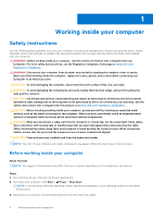
and the contacts. CAUTION: You should only perform troubleshooting and repairs as authorized or directed by the Dell technical assistance team. Damage due to servicing that is not authorized by Dell is not covered by your warranty. See the safety instructions that is shipped with the product or at - Dell OptiPlex 7090 Small Form Factor | Service Manual - Page 7
computer, if applicable. Safety precautions The safety precautions chapter details the primary steps to be taken before performing any disassembly instructions Dell service problems memory integrity, intermittent memory errors, etc. The more difficult type of damage to recognize and troubleshoot - Dell OptiPlex 7090 Small Form Factor | Service Manual - Page 8
service Field Service kits to each service call, Service desktop or portable environment. Servers are typically installed in a rack within a data center; desktops Dell service technicians use the traditional wired ESD grounding wrist strap and protective anti-static mat at all times when servicing Dell - Dell OptiPlex 7090 Small Form Factor | Service Manual - Page 9
sensitive components When transporting ESD sensitive components such as replacement parts or parts to be returned to Dell, it is critical to place these parts in anti-static bags for safe transport. After working inside your computer About this task CAUTION: Leaving stray or loose screws inside your - Dell OptiPlex 7090 Small Form Factor | Service Manual - Page 10
2 Removing and installing components NOTE: The images in this document may differ from your computer depending on the configuration you ordered. Recommended tools The procedures in this document may require the following tools: ● Phillips #0 screwdriver ● Phillips #1 screwdriver ● Plastic scribe - Dell OptiPlex 7090 Small Form Factor | Service Manual - Page 11
Major components of your system 1. Side cover Removing and installing components 11 - Dell OptiPlex 7090 Small Form Factor | Service Manual - Page 12
fan and heat-sink assembly 5. Processor 6. Memory module 7. 2.5-inch hard-drive 8. 2.5/3.5-inch unit 17. M.2 WLAN 18. Speaker NOTE: Dell provides a list of components and their part numbers Follow the procedure in before working inside your computer. NOTE: Ensure that you remove the security - Dell OptiPlex 7090 Small Form Factor | Service Manual - Page 13
Steps 1. Slide the release latch to the right until your hear a click and slide the cover towards the back of the computer. 2. Lift the side cover from the computer. Removing and installing components 13 - Dell OptiPlex 7090 Small Form Factor | Service Manual - Page 14
Installing the side cover Prerequisites If you are replacing a component, remove the existing component before performing the installation procedure. About this task The following image shows the side cover and provides a visual representation of the installation procedure. 14 Removing and - Dell OptiPlex 7090 Small Form Factor | Service Manual - Page 15
cable and disconnect it from the connector on the system board. 2. Slide the intrusion switch and lift it away from the computer . Installing the intrusion switch Prerequisites If you are replacing a component, remove the existing component before performing the installation procedure. Removing and - Dell OptiPlex 7090 Small Form Factor | Service Manual - Page 16
steps 1. Install the side cover. 2. Follow the procedure in after working inside your computer. Front bezel Removing the front bezel Prerequisites 1. Follow the procedure in before working inside your computer. 2. Remove the side cover. About this task The following images indicate the location of - Dell OptiPlex 7090 Small Form Factor | Service Manual - Page 17
Steps 1. Gently pry and release the front-cover tabs sequentially from the top. 2. Rotate the front cover outward from the chassis. 3. Remove the front bezel from the chassis. Installing the front bezel Prerequisites If you are replacing a component, remove the existing component before performing - Dell OptiPlex 7090 Small Form Factor | Service Manual - Page 18
18 Removing and installing components - Dell OptiPlex 7090 Small Form Factor | Service Manual - Page 19
. Hard drive Removing the 2.5/3.5-inch hard-drive caddy Prerequisites 1. Follow the procedure in before working inside your computer. 2. Remove the side cover. 3. Remove the front bezel. About this task The following images indicate the location of the 2.5/3.5-inch hard-drive caddy and provide - Dell OptiPlex 7090 Small Form Factor | Service Manual - Page 20
of the hard drive to avoid errors during installation. Removing the 2.5-inch hard-drive Prerequisites 1. Follow the procedure in before working inside your computer. 2. Remove the side cover. 3. Remove the front bezel. 4. Remove the 2.5/3.5-inch hard-drive caddy. About this task The following images - Dell OptiPlex 7090 Small Form Factor | Service Manual - Page 21
Steps 1. Pull the two tabs from the hard-drive caddy away from the hard-drive. 2. Slide the hard-drive towards the right to free it from the mounting points on the caddy and lift it away from the system. Installing the 2.5/3.5-inch hard-drive caddy Prerequisites If you are replacing a component, - Dell OptiPlex 7090 Small Form Factor | Service Manual - Page 22
until it clicks into place. NOTE: Use the arrows seen on the caddy as guides to identify the tabs on the tray. 2. Connect the hard-drive data and power side cover. 3. Follow the procedure in after working inside your computer. Installing the 2.5-inch hard-drive Prerequisites If you are replacing a - Dell OptiPlex 7090 Small Form Factor | Service Manual - Page 23
Next steps 1. Install the 2.5/3.5-inch hard-drive caddy. 2. Install the front bezel. 3. Install the side cover. 4. Follow the procedure in after working inside your computer. Solid-state drive Removing the M.2 2230 solid-state drive Prerequisites 1. Follow the procedure in before working inside your - Dell OptiPlex 7090 Small Form Factor | Service Manual - Page 24
Steps 1. Remove the single (M2x3) screw that secures the solid-state drive to the system board. 2. Slide and lift the solid-state drive off the system board. Installing the M.2 2230 solid-state drive Prerequisites If you are replacing a component, remove the existing component before performing the - Dell OptiPlex 7090 Small Form Factor | Service Manual - Page 25
side cover. 4. Follow the procedure in after working inside your computer. Removing the M.2 2280 solid-state drive Prerequisites 1. Follow the procedure in before working inside your computer. 2. Remove the side cover. 3. Remove the front bezel. 4. - Dell OptiPlex 7090 Small Form Factor | Service Manual - Page 26
Steps 1. Unroute the SATA cable from the routing guide on metal bracket. 2. Remove the two (6x32) screws securing the metal bracket and lift it away from the system. 3. Remove the screw (M2x3) that secures - Dell OptiPlex 7090 Small Form Factor | Service Manual - Page 27
board. 4. Re-route the SATA cables through the cable management tab. 5. Replace the two screws (6x32) to secure the metal bracket to the computer. Next steps 1. Install the 2.5/3.5-inch hard-drive caddy. 2. Install the front bezel. 3. Install the side cover. 4. Follow the procedure in after working - Dell OptiPlex 7090 Small Form Factor | Service Manual - Page 28
Optical drive Removing the hard-drive and optical-drive bracket Prerequisites 1. Follow the procedure in before working inside your computer. 2. Remove the side cover. 3. Remove the front bezel. 4. Remove the 2.5/3.5-inch hard-drive caddy. About this task The following images indicate the location - Dell OptiPlex 7090 Small Form Factor | Service Manual - Page 29
top portion of the chassis. 6. Disconnect the power and SATA cables from the optical drive and lift the bracket away from the computer. Installing the hard-drive and optical-drive bracket Prerequisites If you are replacing a component, remove the existing component before performing the installation - Dell OptiPlex 7090 Small Form Factor | Service Manual - Page 30
30 Removing and installing components - Dell OptiPlex 7090 Small Form Factor | Service Manual - Page 31
-drive power and SATA cables through the routing guide on the lock. Next steps 1. Install the 2.5/3.5-inch hard-drive caddy. 2. Install the front bezel. 3. Install the side cover. 4. Follow the procedure in after working inside your computer. Removing the slim optical-drive Prerequisites 1. Follow - Dell OptiPlex 7090 Small Form Factor | Service Manual - Page 32
3. Remove the front bezel. About this task The following images show the slim optical-drive and provide a visual representation of the removal procedure. Steps 1. Press the tab on the optical drive to release the optical drive from the hard-drive and optical drive bracket. 2. Slide the optical - Dell OptiPlex 7090 Small Form Factor | Service Manual - Page 33
. SD-card reader Removing the SD-card reader Prerequisites 1. Follow the procedure in before working inside your computer. 2. Remove the side cover. 3. Remove the front bezel. 4. Remove the 2.5/3.5-inch hard-drive caddy. 5. Remove the hard-drive and optical-drive bracket. Removing and installing - Dell OptiPlex 7090 Small Form Factor | Service Manual - Page 34
of the removal procedure. Steps 1. Unroute the PSU cable from the routing guides on the SD-card reader bracket. 2. Remove the two screws (M3x5) that secure the SD-card bracket to the system board and computer. 3. Lift the SD-card reader from the connector on the system board. Installing - Dell OptiPlex 7090 Small Form Factor | Service Manual - Page 35
on the system board. 2. Install the two screws (M3x5) that secure the SD-card bracket to the system board and computer. 3. Reroute the cables through the routing guides on the SD-card reader bracket. Next steps 1. Install the 2.5/3.5-inch hard-drive caddy. 2. Install the hard-drive and optical - Dell OptiPlex 7090 Small Form Factor | Service Manual - Page 36
Steps 1. Remove the screw (M2x3) that secures the wireless card to the system board. 2. Slide and lift the wireless-card bracket off the wireless card. 3. Disconnect the antenna cables from the wireless card. 4. Slide and remove the wireless card at an angle from the wireless-card slot. Installing - Dell OptiPlex 7090 Small Form Factor | Service Manual - Page 37
the antenna cables to the WLAN card. The following table provides the antenna-cable color scheme for the WLAN card of your computer. Table 2. Antenna-cable color scheme Connectors on the wireless card Main (white triangle) Antenna-cable color White Auxiliary (black triangle) Black 2. Slide - Dell OptiPlex 7090 Small Form Factor | Service Manual - Page 38
. Fan and heat-sink assembly Removing the fan and heat-sink assembly Prerequisites 1. Follow the procedure in before working inside your computer. 2. Remove the side cover. 3. Remove the front bezel. About this task The following images indicate the location of the fan and heat-sink assembly and - Dell OptiPlex 7090 Small Form Factor | Service Manual - Page 39
bezel. 2. Install the side cover. 3. Follow the procedure in after working inside your computer. Graphics card Removing the graphics card Prerequisites 1. Follow the procedure in before working inside your computer. 2. Remove the side cover. About this task The following images indicate the location - Dell OptiPlex 7090 Small Form Factor | Service Manual - Page 40
Steps 1. Lift the pull tab and open the expansion-card door. 2. Push and hold the securing tab on the graphics-card slot and lift the graphics card from the PCIe x16 card slot. Installing the graphics card Prerequisites If you are replacing a component, remove the existing component before - Dell OptiPlex 7090 Small Form Factor | Service Manual - Page 41
the expansion-card door, and press until it clicks into place. Next steps 1. Install the side cover. 2. Follow the procedure in after working inside your computer. Coin-cell battery Removing the coin-cell battery Prerequisites 1. Follow the procedure in before working inside your - Dell OptiPlex 7090 Small Form Factor | Service Manual - Page 42
3. Remove the graphics card. About this task The following images indicate the location of the coin-cell battery and provide a visual representation of the removal procedure. Steps 1. Using a plastic scribe, push the coin-cell battery securing-clip on the coin-cell battery socket to release the - Dell OptiPlex 7090 Small Form Factor | Service Manual - Page 43
. 2. Install the side cover. 3. Follow the procedure in after working inside your computer. Memory modules Removing the memory modules Prerequisites 1. Follow the procedure in before working inside your computer. 2. Remove the side cover. 3. Remove the 2.5/3.5-inch hard-drive caddy. 4. Remove the - Dell OptiPlex 7090 Small Form Factor | Service Manual - Page 44
your fingertips to carefully spread apart the securing-clips on each end of the memory-module slot. 2. Grasp the memory module near the securing clip, and then gently ease the memory module out of the memory-module slot. NOTE: Grasp the memory module near the securing clip, and then gently ease the - Dell OptiPlex 7090 Small Form Factor | Service Manual - Page 45
clips return to the locked position. If you do not hear the click, remove the memory module and reinstall it. NOTE: Repeat step 1 to step 3 when installing more than one memory module in your computer. Next steps 1. Install the 2.5/3.5-inch hard-drive caddy. 2. Install the side cover. 3. Follow the - Dell OptiPlex 7090 Small Form Factor | Service Manual - Page 46
CAUTION: For maximum cooling of the processor, do not touch the heat transfer areas on the heat sink. The oils in your skin can reduce the heat transfer capability of the thermal grease. About this task The following images indicate the location of the processor and provide a visual representation - Dell OptiPlex 7090 Small Form Factor | Service Manual - Page 47
About this task The following image indicates the location of the processor and provides a visual representation of the installation procedure. Steps 1. Ensure that the release lever on the processor socket is fully extended in the open position. 2. Align the notches on the processor with the tabs - Dell OptiPlex 7090 Small Form Factor | Service Manual - Page 48
the power-button head and slide the power-button cable out from the front-side chassis of the computer. 3. Pull the power-button cable out from the computer. Installing the power button Prerequisites If you are replacing a component, remove the existing component before performing the installation - Dell OptiPlex 7090 Small Form Factor | Service Manual - Page 49
power button and provide a visual representation of the installation procedure. Steps 1. Insert the power-button cable into the slot from the front-side of the computer, and press the power-button head until it clicks into the place in the chassis. 2. Align and connect the power-button cable to the - Dell OptiPlex 7090 Small Form Factor | Service Manual - Page 50
About this task The following images indicate the location of the power-supply unit and provide a visual representation of the removal procedure. 50 Removing and installing components - Dell OptiPlex 7090 Small Form Factor | Service Manual - Page 51
Removing and installing components 51 - Dell OptiPlex 7090 Small Form Factor | Service Manual - Page 52
the optical-drive SATA cables from the retention clip on the support bracket. 2. Remove the two screws (M6X32) and slide the support bracket out from the slot. 3. Disconnect and unroute the power-supply cable from the routing guides on the chassis. 4. Remove the three screws (M6X32) that secure the - Dell OptiPlex 7090 Small Form Factor | Service Manual - Page 53
Removing and installing components 53 - Dell OptiPlex 7090 Small Form Factor | Service Manual - Page 54
54 Removing and installing components - Dell OptiPlex 7090 Small Form Factor | Service Manual - Page 55
through routing guides and connect it to the connectors on the system board. 5. Place the support bracket into the computer. System board System board callouts - 7090 Small Form Factor 1. Video connector 2. Intrusion switch connector 3. ATX CPU power connector 4. Processor fan connector 5. Memory - Dell OptiPlex 7090 Small Form Factor | Service Manual - Page 56
the system board Prerequisites 1. Follow the procedure in before working inside your computer. 2. Remove the side cover. 3. Remove the front bezel. 4. Remove the WLAN card. 8. Remove the fan assembly. 9. Remove the memory modules. 10. Remove the processor. About this task The following images - Dell OptiPlex 7090 Small Form Factor | Service Manual - Page 57
Removing and installing components 57 - Dell OptiPlex 7090 Small Form Factor | Service Manual - Page 58
58 Removing and installing components - Dell OptiPlex 7090 Small Form Factor | Service Manual - Page 59
32) that secures the front I/O bracket to the chassis. 2. Lift the front I/O panel away from the chassis. 3. Unroute the SATA cables from the cable routing guide on the metal bracket. 4. Remove the two (6-32) screws from the metal bracket from over the M.2 SSD slot and lift it away from the system - Dell OptiPlex 7090 Small Form Factor | Service Manual - Page 60
60 Removing and installing components - Dell OptiPlex 7090 Small Form Factor | Service Manual - Page 61
Steps 1. Align and lower the system board into the system until the stand-off points at the back of the system board align with those on the chassis. 2. Replace the four screws (6-32) and the single standoff screw (M2X4) screw to secure the system board to the chassis. 3. Connect the following - Dell OptiPlex 7090 Small Form Factor | Service Manual - Page 62
install the two (6-32) screws. 5. Route the SATA cables along the cable routing guide on the metal bracket. 6. Align and lower the I/O panel into the slot the WLAN card. 4. Install the solid-state drive. 5. Install the memory modules. 6. Install the graphics card. 7. Install the 2.5/3.5-inch hard- - Dell OptiPlex 7090 Small Form Factor | Service Manual - Page 63
3 Software This chapter details the supported operating systems along with instructions on how to install the drivers. Drivers and downloads When troubleshooting, downloading or installing drivers it is recommended that you read the Dell Knowledge Based article, Drivers and Downloads FAQ SLN128938. - Dell OptiPlex 7090 Small Form Factor | Service Manual - Page 64
for the following purposes: ● Get information about the hardware installed in your computer, such as the amount of RAM and the size of the hard drive , and enabling or disabling base devices. Boot menu Press when the Dell logo appears to initiate a one-time boot menu with a list of the valid - Dell OptiPlex 7090 Small Form Factor | Service Manual - Page 65
the Dell logo computer. Express Service Code Displays the express service code of the computer. Memory Information Memory Installed Displays the total computer memory installed. Memory Available Displays the total computer memory available. Memory Speed Displays the memory speed. Memory - Dell OptiPlex 7090 Small Form Factor | Service Manual - Page 66
64-bit technology is used. Device Information SATA-0 Displays the SATA device information of the computer. SATA-1 Displays the SATA device information of the computer. M.2 PCIe SSD-2 Displays the M.2 PCIe SSD information of the computer. LOM MAC Address Displays the LOM MAC address of the - Dell OptiPlex 7090 Small Form Factor | Service Manual - Page 67
Port Enable or disable the front USB ports. Enable rear USB Port Enable or disable the rear USB ports. Front USB Configuration Enable or disable the front USB ports of the optional Computrace(R) Service from Absolute Software. Admin Disables the master password support. Hard Disk passwords need - Dell OptiPlex 7090 Small Form Factor | Service Manual - Page 68
Enclave Memory Size Set the Intel Software Guard Extensions Enclave Reserve Memory Size. Performance Multi Core Support Enable Enable the USB devices to wake the computer from Standby. Enables you to control the Deep Sleep mode support. Enables the computer to be powered on by special LAN - Dell OptiPlex 7090 Small Form Factor | Service Manual - Page 69
System setup options-Virtualization Support menu Virtualization Support Virtualization Specify whether a options-Maintenance menu Maintenance Service Tag Display the system's Service Tag. Asset Tag Create SupportAssist System Resolution Console and for Dell OS Recovery tool. Overview This - Dell OptiPlex 7090 Small Form Factor | Service Manual - Page 70
the unit's ownership was transferred to the end user. ● Express Service Code - An alternative to Service Tag, 11- digit numerical identification number for the computer. ● Ownership Tag ● Signed Firmware Update - This helps to verify that only Dell Signed and released BIOS can be installed on the - Dell OptiPlex 7090 Small Form Factor | Service Manual - Page 71
memory available for use on the computer. ● Wi-Fi Device - This field mentions the type of wireless device available for use on the computer. ● Native Resolution - This field mentions the native video resolution supported on the computer option - Allows the user to manually add a Boot path. Secure - Dell OptiPlex 7090 Small Form Factor | Service Manual - Page 72
USB settings on the computer. The options available are as follows(All options are enabled by default): ● Enable Front USB Ports ● Enable Rear USB Ports ● Enable USB Boot Support This section allows the user to manually enable the 4 USB ports on the front bezel (All USB ports are enabled by default - Dell OptiPlex 7090 Small Form Factor | Service Manual - Page 73
manually enable the 4 USB ports on the back (All USB ports are enabled by default.). The options are: ● Rear Port 1 (Top Left) ● Rear Port 2 (Left Middle) ● Rear Port 3 (Bottom Left) ● Rear Port 4 (Bottom Right) ● Rear Port 4 (Middle Right) ● Rear Port SATA is setup to support RAID (Intel Rapid - Dell OptiPlex 7090 Small Form Factor | Service Manual - Page 74
default). This section provides information about the connected and active drives on the computer. The following options are available: ● M.2 PCIe SSD-0 ○ Type ○ /disable Multi-Display. (disabled by default). This feature is only supported on Windows 7 and above. This section allows the user to - Dell OptiPlex 7090 Small Form Factor | Service Manual - Page 75
to enable or disable WLAN and Bluetooth on the computer. The options are as follows: ● WLAN Host Configuration Protocol) Selected by default. ● Manual Mode - HTTP(s) Boot reads Boot URL provided to allow the user to enable or disable USB Wake Support. It allows the system to use USB devices like - Dell OptiPlex 7090 Small Form Factor | Service Manual - Page 76
S5 (Selected by default) This section contains a toggle switch to allow the user to enable or disable Intel Speed Shift Technology support. This feature enables the operating system to select appropriate processor performance automatically (ON by default). Description This section contains a toggle - Dell OptiPlex 7090 Small Form Factor | Service Manual - Page 77
read the cycles etc. All of the system memory is encrypted by the TME block attached to the memory controller This field controls the chassis intrusion feature the BIOS module interface of the optional Absolute Persistence Module service from Absolute Software. The options available are as follows: - Dell OptiPlex 7090 Small Form Factor | Service Manual - Page 78
application permission and close when permission ends. Can be disabled by using the F9 camera mute key(LED on). This is the default selected option. ● Manual Shutter Control - Shutter opens when F9 key is pressed(LED off) and closes when F9 key is pressed(LED on) Description This field allows the - Dell OptiPlex 7090 Small Form Factor | Service Manual - Page 79
which allows the user to disable active password support (OFF by default). Update Recovery This BIOSConnect BIOSConnect Dell Auto OS Recovery Threshold Dell Auto OS the user to enable or disable BIOSConnect setup to attempt cloud Service OS recovery if the main operating system fails to boot - Dell OptiPlex 7090 Small Form Factor | Service Manual - Page 80
Auto On Time Auto On Time SERR Messages First Power On Date Description ● Off ●1 ● 2 (selected by default) ●3 Description This field provides the unique Service Tag of the computer. This field provides the asset tag which is a unique and up to 64-character identification that can be set by the IT - Dell OptiPlex 7090 Small Form Factor | Service Manual - Page 81
provides Performance settings. Table 27. Performance Options Multi-Core Support Active Cores Intel SpeedStep Enable Intel SpeedStep Technology C-States This field allows the user to configure the number of active cores on the computer. The options are as follows: ● All Cores (selected by default) ●1 - Dell OptiPlex 7090 Small Form Factor | Service Manual - Page 82
known this can result in data loss or an unnecessary operating system re-install. For more information on this subject, see Knowledge Article: https:// www.dell.com/support/article/sln153694 82 System setup - Dell OptiPlex 7090 Small Form Factor | Service Manual - Page 83
.dell.com/support. 2. Click Product support. In the Search support box, enter the Service Tag of your computer, and then click Search. NOTE: If you do not have the Service Tag, use the SupportAssist feature to automatically identify your computer. You can also use the product ID or manually browse - Dell OptiPlex 7090 Small Form Factor | Service Manual - Page 84
from the Dell Support website and copied to the root of the USB drive ● AC power adapter that is connected to the computer ● Functional computer battery to USB drive where you copied the flash into a USB port of the computer. 2. Turn on the computer and press F12 to access the One-Time Boot Menu, - Dell OptiPlex 7090 Small Form Factor | Service Manual - Page 85
new password field and click OK. 4. Press Esc and a message prompts you to save the changes. 5. Press Y to save the changes. The computer reboots. Deleting or changing an existing system setup password Prerequisites Ensure that the Password Status is Unlocked (in the System Setup) before attempting - Dell OptiPlex 7090 Small Form Factor | Service Manual - Page 86
CPU failure ● Run the Dell Support Assist/Dell Diagnostics tool. ● If problem persists, replace the system board. System board failure (included ● BIOS corruption or ROM ● error) Flash latest BIOS version If problem persists, replace the system board. No memory/RAM detected ● Confirm that - Dell OptiPlex 7090 Small Form Factor | Service Manual - Page 87
it from the Dell Support website to troubleshoot and fix your computer when it fails to boot into their primary operating system due to software or hardware failures. For more information about the Dell SupportAssist OS Recovery, see Dell SupportAssist OS Recovery User's Guide at www.dell.com - Dell OptiPlex 7090 Small Form Factor | Service Manual - Page 88
BIOS: Steps 1. Turn on your computer. 2. Go to www.dell.com/support. 3. Click Product support, enter the Service Tag of your computer, and then click Search. NOTE: If you do not have the Service Tag, use the product ID or manually browse for your computer model. 4. Click Drivers & downloads > Find - Dell OptiPlex 7090 Small Form Factor | Service Manual - Page 89
to drain the flea power. 6. Install the battery. 7. Install the base cover. 8. Connect the power adapter to your computer. 9. Turn on your computer. NOTE: For more information about performing a hard reset, see the knowledge base article 000130881 at www.dell.com/support. Troubleshooting 89 - Dell OptiPlex 7090 Small Form Factor | Service Manual - Page 90
more about your computer through videos, manuals and documents. Your Dell computer is uniquely identified by a Service Tag or Express Service Code. To view relevant support resources for your Dell computer, enter the Service Tag or Express Service Code at www.dell.com/support. For more information
-
 1
1 -
 2
2 -
 3
3 -
 4
4 -
 5
5 -
 6
6 -
 7
7 -
8
-
9
-
10
-
11
-
12
-
13
-
14
-
15
-
16
-
17
-
18
-
19
-
20
-
21
-
22
-
23
-
24
-
25
-
26
-
27
-
28
-
29
-
30
-
31
-
32
-
33
-
34
-
35
-
36
-
37
-
38
-
39
-
40
-
41
-
42
-
43
-
44
-
45
-
46
-
47
-
48
-
49
-
50
-
51
-
52
-
53
-
54
-
55
-
56
-
57
-
58
-
59
-
60
-
61
-
62
-
63
-
64
-
65
-
66
-
67
-
68
-
69
-
70
-
71
-
72
-
73
-
74
-
75
-
76
-
77
-
78
-
79
-
80
-
81
-
82
-
83
-
84
-
85
-
86
-
87
-
88
-
89
-
90
 |
 |

OptiPlex 7090 Small Form Factor
Service Manual
Regulatory Model: D15S
Regulatory Type: D15S004
August 2021
Rev. A01