Denon S-5BD Owners Manual - English - Page 67
Rear Panel
 |
UPC - 083795001216
View all Denon S-5BD manuals
Add to My Manuals
Save this manual to your list of manuals |
Page 67 highlights
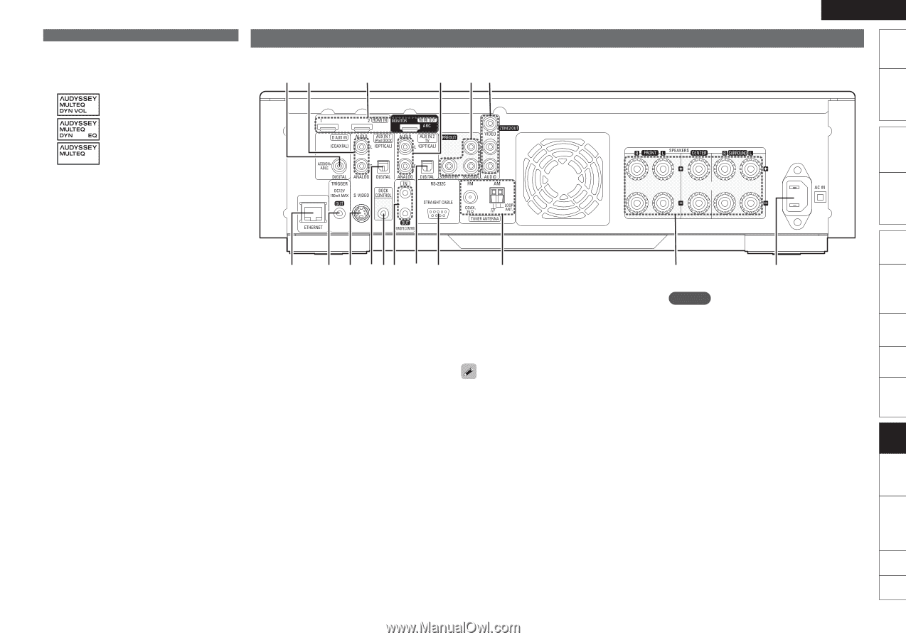
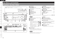
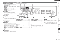
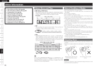
Getting Started Simple Version Connections Playback (Basic) Settings ENGLISH Front Panel / Top Panel / Display W4 AUDYSSEY MULTEQ® indicators Lighting is as follows, depending on the setting of "Dynamic EQ" (vpage 51) and "Dynamic Volume" (vpage 52). When "Dynamic EQ" and "Dynamic Volume" are "ON". When "Dynamic EQ" is "ON" and "Dynamic Volume" is "OFF". When "Dynamic EQ" and "Dynamic Volume" are "OFF". W5 SLEEP indicator This lights when the sleep mode is selected. W6 RESTORER indicator This lights when the RESTORER mode is selected (vpage 26). W7 ZONE2 indicators This lights up when ZONE2 (separate room) power is turned on. W8 AL24 indicator This lights when AL24 Processing (vpage 67) is activated. W9 Input mode indicators Set the audio input modes for the different input sources (vpage 47). E0 HDMI indicator This lights when playing using HDMI connections. E1 Tuner reception mode indicators These light according to the reception conditions when the input source is set to "TUNER". STEREO: In the FM mode, these light when receiving analog stereo broadcasts. TUNED: Lights when the broadcast is properly tuned in. AUTO: These light when in the auto tuning mode. E2 Decoder indicators These light when the respective decoders are operating. Rear Panel See the page indicated in parentheses ( ). Q5 Q3 Q4 Q3 q w e rty r u q ETHERNET connector 16) w TRIGGER OUT jack 17) e S-VIDEO connector 14) r OPTICAL connector 13, 15) t DOCK CONTROL jack 14) y REMOTE CONTROL jacks 17) u RS-232C connector 17) i FM/AM antenna terminals 15) o Speaker terminals 4, 35) Q0 AC inlet (AC IN 5) Q2 Q1 i o Q0 Q1 ZONE2 OUT connectors 41) Q2 PREOUT connectors 35) Q3 Analog audio connectors 13 - 15) Q4 HDMI connectors 12) Q5 COAXIAL connector 13 - 15) NOTE • Do not touch the inner pins of the connectors on the rear panel. Electrostatic discharge may cause permanent damage to the unit. • Do not put your finger or foreign object in the fan opening. Doing so could cause injury or unit failure. When using the COAXIAL connector, set "Manual Setup" - "Audio Setup" - "COAX Input Assign" (vpage 56) on the GUI menu to "AUX1" or "AUX2". Playback (Advanced) Multizone GUI Remote Control Part Names Other Information Troubleshooting Spec. Index 63
-
 1
1 -
2
-
3
-
4
-
5
-
6
-
7
-
8
-
9
-
10
-
11
-
12
-
13
-
14
-
15
-
16
-
17
-
18
-
19
-
20
-
21
-
22
-
23
-
24
-
25
-
26
-
27
-
28
-
29
-
30
-
31
-
32
-
33
-
34
-
35
-
36
-
37
-
38
-
39
-
40
-
41
-
42
-
43
-
44
-
45
-
46
-
47
-
48
-
49
-
50
-
51
-
52
-
53
-
54
-
55
-
56
-
57
-
58
-
59
-
60
-
61
-
 62
62 -
 63
63 -
 64
64 -
 65
65 -
 66
66 -
 67
67 -
 68
68 -
 69
69 -
 70
70 -
 71
71 -
 72
72 -
73
-
74
-
75
-
76
-
77
-
78
-
79
-
80
-
81
-
82
-
83
-
84
-
85
-
86
-
87
-
88
-
89
-
90
-
91
-
92
-
93
-
94
-
95
 |
 |