Gateway FX540X 8512728 - FX540 Hardware Reference Guide - Page 86
hear a click.
 |
View all Gateway FX540X manuals
Add to My Manuals
Save this manual to your list of manuals |
Page 86 highlights
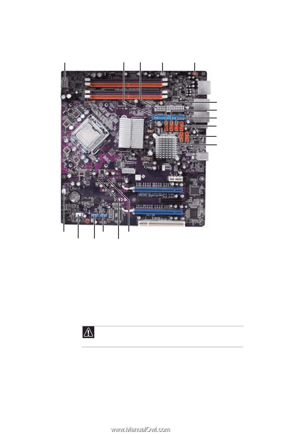
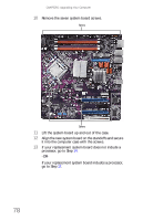
CHAPTER 5: Upgrading Your Computer 17 Connect the power and data cables using your notes from Step 9, or use the following graphic as a guide.. AUX power IDE Power Fan (rear) Front panel audio SATA 6 SATA 5 SATA 4 SATA 3 SATA 1 SATA 2 Fan IEEE1394 Front USB (Front) Fan IEEE1394 Card reader 18 Place the heat sink over the processor, then tighten the screws that secure it to the system board. 19 Align the notches on the memory modules with the notches on the memory module banks and press the modules firmly into the banks. The tabs on the sides of the memory modules should secure the memory modules automatically. When a module is secure, you hear a click. Caution Do not touch the contacts on the bottom part of the expansion card. Touching the contacts can cause electrostatic damage to the card. 20 Install the expansion cards into the expansion slots. You can slightly seesaw a card end-to-end to help insert the card, but do not bend the card sideways. For more details, see "Adding or replacing an expansion card" on page 71. 80
-
 1
1 -
2
-
3
-
4
-
5
-
6
-
7
-
8
-
9
-
10
-
11
-
12
-
13
-
14
-
15
-
16
-
17
-
18
-
19
-
20
-
21
-
22
-
23
-
24
-
25
-
26
-
27
-
28
-
29
-
30
-
31
-
32
-
33
-
34
-
35
-
36
-
37
-
38
-
39
-
40
-
41
-
42
-
43
-
44
-
45
-
46
-
47
-
48
-
49
-
50
-
51
-
52
-
53
-
54
-
55
-
56
-
57
-
58
-
59
-
60
-
61
-
62
-
63
-
64
-
65
-
66
-
67
-
68
-
69
-
70
-
71
-
72
-
73
-
74
-
75
-
76
-
77
-
78
-
79
-
80
-
 81
81 -
 82
82 -
 83
83 -
 84
84 -
 85
85 -
 86
86 -
 87
87 -
 88
88 -
 89
89 -
 90
90 -
 91
91 -
92
-
93
-
94
-
95
-
96
-
97
-
98
-
99
-
100
-
101
-
102
-
103
-
104
-
105
-
106
-
107
-
108
-
109
-
110
-
111
-
112
-
113
-
114
-
115
-
116
-
117
-
118
-
119
-
120
-
121
-
122
-
123
-
124
-
125
-
126
-
127
-
128
-
129
-
130
-
131
-
132
-
133
-
134
-
135
-
136
-
137
-
138
-
139
-
140
-
141
-
142
-
143
-
144
-
145
-
146
-
147
-
148
-
149
-
150
-
151
-
152
-
153
-
154
-
155
-
156
-
157
-
158
-
159
-
160
-
161
-
162
-
163
-
164
 |
 |