HP 1320n HP LaserJet 1160 and 1320 Series - User Guide - Page 166
Appendix D, pointing left and the cutouts should be at the top left and center left.
 |
UPC - 829160407364
View all HP 1320n manuals
Add to My Manuals
Save this manual to your list of manuals |
Page 166 highlights
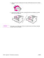
3. Locate the DIMM slot. The cam latches, located at the top and bottom, should rotate outward. 4. Remove the DIMM from the antistatic bag it came in, grasping the DIMM on the top edge. 5. Position the DIMM on the right side of the circuit board. The gold contacts should be pointing left and the cutouts should be at the top left and center left. 156 Appendix D HP parts and accessories ENWW
-
 1
1 -
2
-
3
-
4
-
5
-
6
-
7
-
8
-
9
-
10
-
11
-
12
-
13
-
14
-
15
-
16
-
17
-
18
-
19
-
20
-
21
-
22
-
23
-
24
-
25
-
26
-
27
-
28
-
29
-
30
-
31
-
32
-
33
-
34
-
35
-
36
-
37
-
38
-
39
-
40
-
41
-
42
-
43
-
44
-
45
-
46
-
47
-
48
-
49
-
50
-
51
-
52
-
53
-
54
-
55
-
56
-
57
-
58
-
59
-
60
-
61
-
62
-
63
-
64
-
65
-
66
-
67
-
68
-
69
-
70
-
71
-
72
-
73
-
74
-
75
-
76
-
77
-
78
-
79
-
80
-
81
-
82
-
83
-
84
-
85
-
86
-
87
-
88
-
89
-
90
-
91
-
92
-
93
-
94
-
95
-
96
-
97
-
98
-
99
-
100
-
101
-
102
-
103
-
104
-
105
-
106
-
107
-
108
-
109
-
110
-
111
-
112
-
113
-
114
-
115
-
116
-
117
-
118
-
119
-
120
-
121
-
122
-
123
-
124
-
125
-
126
-
127
-
128
-
129
-
130
-
131
-
132
-
133
-
134
-
135
-
136
-
137
-
138
-
139
-
140
-
141
-
142
-
143
-
144
-
145
-
146
-
147
-
148
-
149
-
150
-
151
-
152
-
153
-
154
-
155
-
156
-
157
-
158
-
159
-
160
-
 161
161 -
 162
162 -
 163
163 -
 164
164 -
 165
165 -
 166
166 -
 167
167 -
 168
168 -
 169
169 -
 170
170 -
 171
171 -
172
-
173
-
174
-
175
-
176
-
177
-
178
-
179
-
180
-
181
-
182
-
183
-
184
 |
 |

3.
Locate the DIMM slot. The cam latches, located at the top and bottom, should rotate
outward.
4.
Remove the DIMM from the antistatic bag it came in, grasping the DIMM on the top edge.
5.
Position the DIMM on the right side of the circuit board. The gold contacts should be
pointing left and the cutouts should be at the top left and center left.
156
Appendix D
HP parts and accessories
ENWW