HP Integrity rx8620 Installation Guide, Sixth Edition - HP Integrity rx8620 Se
HP Integrity rx8620 Manual
 |
View all HP Integrity rx8620 manuals
Add to My Manuals
Save this manual to your list of manuals |
HP Integrity rx8620 manual content summary:
- HP Integrity rx8620 | Installation Guide, Sixth Edition - HP Integrity rx8620 Se - Page 1
Installation Guide HP Integrity rx8620 Server Sixth Edition Manufacturing Part Number : A7026-96037-en May 2007 Printed in the U.S.A. © Copyright 2007 - HP Integrity rx8620 | Installation Guide, Sixth Edition - HP Integrity rx8620 Se - Page 2
HP products and services are set forth in the express warranty statements accompanying such products and services. Nothing herein should be construed as constituting an additional warranty. HP . Added DVD+RW install instructions. Updated I/O card list. Edition Updated lists of supported PCI/PCI-X I/O - HP Integrity rx8620 | Installation Guide, Sixth Edition - HP Integrity rx8620 Se - Page 3
Devices for the HP Integrity rx8620 Server 22 System Backplane 23 I/O Subsystem 24 HP Integrity rx8620 Server Description 28 2. Installation Inspecting the Server Cabinet 32 Receiving the Server Cabinet 33 Securing the Cabinet 36 Rack Mount System Installation 37 Manual Lifting 38 Using - HP Integrity rx8620 | Installation Guide, Sixth Edition - HP Integrity rx8620 Se - Page 4
Contents 4 - HP Integrity rx8620 | Installation Guide, Sixth Edition - HP Integrity rx8620 Se - Page 5
Packing List 42 Table 2-2. HP Integrity rx8620 Server I/O Cards - HP-UX 57 Table 2-3. HP Integrity rx8620 Server I/O Cards - Windows 58 Table 2-4. HP Integrity rx8620 Server - Linux Supported I/O Cards 59 Table 2-5. HP Integrity rx8620 Server - Open VMS Supported I/O Cards 60 Table 2-6. Single - HP Integrity rx8620 | Installation Guide, Sixth Edition - HP Integrity rx8620 Se - Page 6
Tables 6 - HP Integrity rx8620 | Installation Guide, Sixth Edition - HP Integrity rx8620 Se - Page 7
HP Integrity rx8620 Server (front view 11 Figure 1-2. HP Integrity rx8620 Server (front view without bezel 12 Figure 1-3. Front Panel LEDs and Power Switch 12 Figure 1-4. HP Integrity rx8620 Server 16-Socket Block Diagram 14 Figure 1-5. Cell Board 15 Figure 1-6. Memory , rx8620, rx8640 73 Figure - HP Integrity rx8620 | Installation Guide, Sixth Edition - HP Integrity rx8620 Se - Page 8
Figures Figure 2-30. Front Panel Display 78 Figure 2-31. BPS LED Location 79 Figure 2-32. MP Main Menu 80 Figure 2-33. The lc Command Screen 81 Figure 2-34. The ls Command Screen 82 Figure 2-35. Example sa Command 83 Figure 2- - HP Integrity rx8620 | Installation Guide, Sixth Edition - HP Integrity rx8620 Se - Page 9
1 Introduction The HP Integrity rx8620 Server is a member of the HP business-critical computing platform family mid-range, mid-volume servers positioned between the HP Integrity rx7620 and HP Integrity Superdome servers. Chapter 1 9 - HP Integrity rx8620 | Installation Guide, Sixth Edition - HP Integrity rx8620 Se - Page 10
Overview Overview The HP Integrity rx8620 Servers are 17U1 high, 16-socket symmetric multiprocessor (SMP) rack-mount or stand-alone servers that accommodate up to 128GB of memory the server include: • Up to 128GB of physical memory provided by dual in-line memory modules (DIMMs). • Up to 32 - HP Integrity rx8620 | Installation Guide, Sixth Edition - HP Integrity rx8620 Se - Page 11
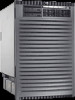
Introduction Overview • Four 220 VAC power plugs. Two are required and the other two provide power source redundancy. Figure 1-1 HP Integrity rx8620 Server (front view) Chapter 1 11 - HP Integrity rx8620 | Installation Guide, Sixth Edition - HP Integrity rx8620 Se - Page 12
Introduction Overview Figure 1-2 HP Integrity rx8620 Server (front view without bezel) Front Panel Front Panel Indicators and Controls The front panel, located on the front of the server, includes a power switch. Refer to Figure 1-3. Enclosure Status LEDs The following status LEDs are on the - HP Integrity rx8620 | Installation Guide, Sixth Edition - HP Integrity rx8620 Se - Page 13
Overview Cell Board The cell board contains the processors, main memory, and the cell controller (CC) application specific integrated circuit (ASIC) that interfaces the processors and memory one to four cell boards installed in an HP Integrity rx8620 Server. A cell board can be selectively powered - HP Integrity rx8620 | Installation Guide, Sixth Edition - HP Integrity rx8620 Se - Page 14
HP Integrity rx8620 Server Description Detailed HP Integrity rx8620 Server Description Figure 1-4 HP Integrity rx8620 Server 16-Socket Block Diagram Cell Board memory cpu cpu cc cpu cpu Cell Board memory cpu cpu cc cpu cpu Cell Board memory cpu cpu cc cpu cpu Cell Board memory - HP Integrity rx8620 | Installation Guide, Sixth Edition - HP Integrity rx8620 Se - Page 15
HP Integrity rx8620 Server Description dependent hardware (PDH) and micro controller hardware. Each cell board holds up to 16 DIMMS. Between one to four cell boards can be installed in the server the four processors • Two memory buses (one going to each half of the main memory array) • Incoming and - HP Integrity rx8620 | Installation Guide, Sixth Edition - HP Integrity rx8620 Se - Page 16
Introduction Detailed HP Integrity rx8620 Server Description Figure 1-6 shows a simplified view of the memory subsystem. It consists of two independent access paths, each path having its own address bus, control bus, data bus, and DIMMs. In practice, the CC - HP Integrity rx8620 | Installation Guide, Sixth Edition - HP Integrity rx8620 Se - Page 17
Introduction Detailed HP Integrity rx8620 Server Description PDH Riser Board The HP Integrity rx8620 Server PDH riser board is a small card that plugs into the cell board at a right angle. The PDH riser interface contains a microprocessor memory interface microcircuit, hardware including the - HP Integrity rx8620 | Installation Guide, Sixth Edition - HP Integrity rx8620 Se - Page 18
1 CPU 0 DIMMS The memory DIMMs used by the HP Integrity rx8620 Server are custom designed by HP and are identical to those used in the Superdome server. Each DIMM contains SDRAM memory components and is qualified to run at 125MHz. The CPU chip set will not support traditional DRAMs. 18 Chapter - HP Integrity rx8620 | Installation Guide, Sixth Edition - HP Integrity rx8620 Se - Page 19
a page closed is 11.5 cycles (92ns), and the latency for a page miss is 14.5 cycles (116ns). Valid Memory Configurations The HP Integrity rx8620 Server is capable of supporting as little as 0.5GB of main memory using two 256MB DIMMs installed on one of the cell boards and as much as 128GB by filling - HP Integrity rx8620 | Installation Guide, Sixth Edition - HP Integrity rx8620 Se - Page 20
Introduction Detailed HP Integrity rx8620 Server Description A quad as seen in Figure 1-8, is a grouping of four DIMMs. Configurations with 8 or 16 DIMM slots loaded are 5A DIMM 1A DIMM 0B DIMM 4B QUAD 0 DIMM 4A DIMM 0A Rear Edge of Cell Board (Plugs into Server Backplane) 20 Chapter 1 - HP Integrity rx8620 | Installation Guide, Sixth Edition - HP Integrity rx8620 Se - Page 21
HP Integrity rx8620 Server Description Cells and nPartitions An nPartition has one or more cells (containing processors and memory the HP Integrity rx8620 Server, each nPartition has its own dedicated portion of the server hardware that may be configured within a server complex, allowing the hardware - HP Integrity rx8620 | Installation Guide, Sixth Edition - HP Integrity rx8620 Se - Page 22
Introduction Detailed HP Integrity rx8620 Server Description Internal Disk Devices for the HP Integrity rx8620 Server As Figure 1-9 shows, in an HP Integrity rx8620 Server cabinet the top internal disk drives connect to cell 0 through the core I/O for cell 0. The bottom internal disk drives connect - HP Integrity rx8620 | Installation Guide, Sixth Edition - HP Integrity rx8620 Se - Page 23
Introduction Detailed HP Integrity rx8620 Server Description System Backplane The system backplane houses the system clock generation logic, the system reset generation logic, DC-to-DC converters, power monitor logic, and - HP Integrity rx8620 | Installation Guide, Sixth Edition - HP Integrity rx8620 Se - Page 24
Introduction Detailed HP Integrity rx8620 Server Description System Backplane to Cell Board into "ropes." A rope is defined as a high-speed, point-to-point data bus. The SBA can support up to 16 of these high-speed bi-directional rope links for a total aggregate bandwidth of approximately 4 - HP Integrity rx8620 | Installation Guide, Sixth Edition - HP Integrity rx8620 Se - Page 25
Description Figure 1-11 PCI-X Board to Cell Board Block Diagram The HP Integrity rx8620 Server supports two internal SBAs. The SBAs generate 32 rope buses (16 per SBA). The 32 available internal rope buses are divided in the following manner: • Two ropes are routed as single rope bundles to - HP Integrity rx8620 | Installation Guide, Sixth Edition - HP Integrity rx8620 Se - Page 26
either the 66MHz or 133MHz PCI-X frequency is supported. b. This is a single rope between the SBA and LBA and not a dual rope like that seen for ropes 1-7. Core I/O Card Up to two core I/O cards can be plugged into the HP Integrity rx8620 Server. Two core I/O cards allows for two I/O partitions to - HP Integrity rx8620 | Installation Guide, Sixth Edition - HP Integrity rx8620 Se - Page 27
, having connectors and termination logic. All hard disks are hot-plug while removable media disks are not hot-plug. The HP Integrity rx8620 Server accommodates two internal, removable media devices. Therefore, power connectors for a removable media device are required on the mass storage backplane - HP Integrity rx8620 | Installation Guide, Sixth Edition - HP Integrity rx8620 Se - Page 28
Introduction Detailed HP Integrity rx8620 Server Description HP Integrity rx8620 Server Description Dimensions and Components Figure 1-13 HP Integrity rx8620 Server (Front View) Removable Media Drive PCI Power Supply Power Switch Hard Disk Drive Front OLR Fan Bulk Power Supply • Depth: - HP Integrity rx8620 | Installation Guide, Sixth Edition - HP Integrity rx8620 Se - Page 29
fans. Redundant line cords attach to the AC power receptacles at the bottom rear. Two 20-amp cords are required to power the HP Integrity rx8620 Server. Two additional line cords provide redundancy. Access the system backplane by removing the left side cover. The system backplane hinges from the - HP Integrity rx8620 | Installation Guide, Sixth Edition - HP Integrity rx8620 Se - Page 30
Introduction Detailed HP Integrity rx8620 Server Description 30 Chapter 1 - HP Integrity rx8620 | Installation Guide, Sixth Edition - HP Integrity rx8620 Se - Page 31
2 Installation Inspect shipping containers when the equipment arrives at the site. Check equipment after the packing has been removed. This chapter discusses how to inspect and receive the HP Integrity rx8620 Server. Chapter 2 31 - HP Integrity rx8620 | Installation Guide, Sixth Edition - HP Integrity rx8620 Se - Page 32
Server Cabinet Inspecting the Server Cabinet NOTE The server will ship in one of three different configurations. The configurations are: • on a pallet installed in a server as a standalone server HP shipping containers are Examine the server cabinet until Field Services turns the HP Installation Specialist - HP Integrity rx8620 | Installation Guide, Sixth Edition - HP Integrity rx8620 Se - Page 33
and cause serious eye injury. NOTE Position the pallet, allowing for enough space to roll the cabinet off the pallet before starting. Remove the server cabinet using the following steps: Step 1. Cut the polystrap bands around the shipping container. Step 2. Lift the cardboard top cap from the - HP Integrity rx8620 | Installation Guide, Sixth Edition - HP Integrity rx8620 Se - Page 34
Installation Receiving the Server Cabinet Step 4. Remove the packing materials. CAUTION The plastic wrapping material should be cut off rather than pulled off. Pulling the plastic covering off represents - HP Integrity rx8620 | Installation Guide, Sixth Edition - HP Integrity rx8620 Se - Page 35
Step 6. Remove the six bolts from the base attaching the rack to the pallet. Figure 2-3 Preparing to Roll Off the Pallet Installation Receiving the Server Cabinet WARNING Be sure that the leveling feet on the rack are raised before you roll the rack down the ramp, and any time you - HP Integrity rx8620 | Installation Guide, Sixth Edition - HP Integrity rx8620 Se - Page 36
Installation Receiving the Server Cabinet Securing the Cabinet When in position, secure and stabilize the cabinet using the leveling feet at the corners of the base and install the anti-tip mechanisms on the bottom front and rear of the rack. Figure 2-4 Securing the Cabinet 36 Chapter 2 - HP Integrity rx8620 | Installation Guide, Sixth Edition - HP Integrity rx8620 Se - Page 37
handles are the same part. Refer to service note A6093A-11. This is the same accessory kit used for the HP 9000 rp8400 server. There are several documents written to help with rack mounting the server. This list is intended to guide the HP Installation Specialist to the documentation that has been - HP Integrity rx8620 | Installation Guide, Sixth Edition - HP Integrity rx8620 Se - Page 38
Instructions for removing and re-installing these components can be found in the Removal and Replacement chapter of the HP Service Guide for the HP Integrity rx8620 Server 3. Ensure the vertical support brackets are in the down position so they rest on the slides when the server is lowered to the - HP Integrity rx8620 | Installation Guide, Sixth Edition - HP Integrity rx8620 Se - Page 39
the same cabinet while installing or servicing either an HP Integrity rx8620 Server or another server product. Failure to follow these instructions could result in the cabinet tipping over. Step 1. Obtain the HP J1528A Rack Integration Kit Installation Guide before proceeding with the rack mount - HP Integrity rx8620 | Installation Guide, Sixth Edition - HP Integrity rx8620 Se - Page 40
Pallet Position the Lifter Forks at These Insertion Points Step 4. Carefully roll the lift forward until it is fully positioned against the side of the server. 40 Chapter 2 - HP Integrity rx8620 | Installation Guide, Sixth Edition - HP Integrity rx8620 Se - Page 41
away from the pallet. Do not raise the server any higher than necessary when moving it over to the rack. Step 7. Follow the HP J1528A Rack Integration Kit Installation Guide to complete these steps: • Mounting the server to the slides • Installing the cable management arm (CMA) • Installing the - HP Integrity rx8620 | Installation Guide, Sixth Edition - HP Integrity rx8620 Se - Page 42
Installation Wheel Kit Installation Wheel Kit Installation Compare the packing list with the contents of the wheel kit before beginning the installation. Table 2-1 Wheel Kit Packing List Part Number A9904-04002 A9904-04007 A9904-04008 A9904-04009 A6093-04082 A6093-04083 A6093-04084 A6093-04085 - HP Integrity rx8620 | Installation Guide, Sixth Edition - HP Integrity rx8620 Se - Page 43
Installation 1. Cut and remove the polystrap bands securing the server to the pallet. 2. Lift the carton top from the cardboard tray resting on the pallet. 3. Remove the bezel kit carton and top cushion from the pallet. Figure 2-7 Server on Shipping Pallet Top Cushions Bezel Kit 4. Unfold bottom - HP Integrity rx8620 | Installation Guide, Sixth Edition - HP Integrity rx8620 Se - Page 44
Installation Wheel Kit Installation 5. Remove the front cushion only. Do not remove any other cushions until further instructed. Figure 2-8 Removal of Cushion from Front Edge of Server Rear Cushion Side Cushion Front Cushion 6. Open the wheel kit box and locate the two front casters. The front - HP Integrity rx8620 | Installation Guide, Sixth Edition - HP Integrity rx8620 Se - Page 45
the eight screws from the plastic pouch. Attach one wheel caster to the front of the server. Figure 2-9 Attaching a Caster Wheel to the Server Front Caster 8. Attach the remaining front caster to the server using two more screws supplied in the plastic pouch. 9. Remove the rear cushion at the rear - HP Integrity rx8620 | Installation Guide, Sixth Edition - HP Integrity rx8620 Se - Page 46
Installation Wheel Kit Installation 12. Attach the ramp to the edge of the pallet. Note there are two pre-drilled holes in the ramp. Use the two screws taped to the ramp and attach it to the pallet. Figure 2-10 Attaching the Ramp to the Pallet Pre-drilled Holes 46 Chapter 2 - HP Integrity rx8620 | Installation Guide, Sixth Edition - HP Integrity rx8620 Se - Page 47
unfold the cardboard tray so that it lays flat on the pallet. Figure 2-11 Side Cushion Removal from Server Side Cushion Ramp 14. Carefully roll the server off the pallet and down the ramp. 15. Obtain the caster covers from the wheel kit. Note that the caster covers are designed to fit - HP Integrity rx8620 | Installation Guide, Sixth Edition - HP Integrity rx8620 Se - Page 48
Insert the slot on the caster cover into the front caster. Secure the caster cover to the server by tightening the captive screw on the cover at the rear of the server. Figure 2-12 Securing each Caster Cover to the Server Captive Screw Caster Covers Rear Casters Front Casters Slot 48 Chapter 2 - HP Integrity rx8620 | Installation Guide, Sixth Edition - HP Integrity rx8620 Se - Page 49
Installation Wheel Kit Installation 17. Wheel kit installation is complete after both caster covers are attached to the server and the bezel cover is snapped into place on the front of the server. Figure 2-13 Completed Wheel Kit Installation Attached Caster Cover Chapter 2 49 - HP Integrity rx8620 | Installation Guide, Sixth Edition - HP Integrity rx8620 Se - Page 50
Installation Wheel Kit Installation Top and Side Cover Installation NOTE It may be necessary to remove existing top and side covers installed on the server before installing the covers shipped with the wheel kit. If cover removal is not needed, go directly to the sections for installing the top - HP Integrity rx8620 | Installation Guide, Sixth Edition - HP Integrity rx8620 Se - Page 51
Step 5. Place the cover in a safe location. Figure 2-15 Top Cover Detail Installation Wheel Kit Installation Retaining Screw Installing the Top Cover Step 1. Orient the cover according to its position on the chassis. Step 2. Slide the cover into position using a slow, firm pressure to properly - HP Integrity rx8620 | Installation Guide, Sixth Edition - HP Integrity rx8620 Se - Page 52
Installation Wheel Kit Installation Removing the Side Cover Figure 2-16 Side Cover Detail Retaining Screw Step 1. Connect to ground with a wrist strap. Step 2. Loosen the blue retaining screw securing the cover to the chassis. See Figure 2-16. Step 3. Slide the cover from the chassis toward the - HP Integrity rx8620 | Installation Guide, Sixth Edition - HP Integrity rx8620 Se - Page 53
are two 60A PDUs available for the HP Integrity rx8620 Server. Each PDU is mounted horizontally between the rear columns of the server cabinet. The 60A PDUs are delivered with outside HP. The PDU installation kit contains the: • PDU with cord and plug • Mounting hardware • Installation instructions - HP Integrity rx8620 | Installation Guide, Sixth Edition - HP Integrity rx8620 Se - Page 54
these procedures. Failure to follow ESD safety precautions could result in damage to the HP Integrity rx8620 Server. The following options can be installed in the HP Integrity rx8620 Server: • PCI I/O cards • additional hard disk drive storage • additional removable media device storage Installing - HP Integrity rx8620 | Installation Guide, Sixth Edition - HP Integrity rx8620 Se - Page 55
must be turned off before attempting to install it. Refer to "Shutting Down nPartitions and Powering Off Hardware Components" in the Service Guide for the HP Integrity rx8620 Server for more information. If an upper drive is installed, it will need to be removed before installing a lower drive. Step - HP Integrity rx8620 | Installation Guide, Sixth Edition - HP Integrity rx8620 Se - Page 56
Installation Installing Accessories Step 2. Connect the cables to the rear of the drive. Step 3. Install left and right media rails and clips. Step 4. Slide the drive in the chassis. Fold the cables out of the way. Step 5. The drive easily slides into the chassis; however, a slow, firm pressure is - HP Integrity rx8620 | Installation Guide, Sixth Edition - HP Integrity rx8620 Se - Page 57
cards are supported in the HP Integrity rx8620 Server. Known supported cards at the release of this manual are shown in Tables 3-1 through 3-4. Table 2-2 HP Integrity rx8620 Server I/O Cards - HP-UX Part Obsidian USB/VGA PCI card 1 PCI-X 2 port 1000BaseSX Dual Port (Intel chip) 16 Chapter 2 57 - HP Integrity rx8620 | Installation Guide, Sixth Edition - HP Integrity rx8620 Se - Page 58
Installation Installing Accessories Table 2-2 HP Integrity rx8620 Server I/O Cards - HP-UX (Continued) Part Number Card Description Number of Cards Supported (B-Bootable) A7012A PCI-X 2 port 1000BaseT Dual Port (Intel chip) 16 A7173A 2 port U320 SCSI 16B A9782A PCI-X 1000B-T GB FC GigE- - HP Integrity rx8620 | Installation Guide, Sixth Edition - HP Integrity rx8620 Se - Page 59
Exulex 4GB DC NIC Broadcom Cu NIC Broadcom FC NIC Intel Dual Cu NIC Intel Dual FC 10G NIC Number of Cards Supported (B-Bootable) 1 1 8B 8B 8B 8B 8 8 12B 8B 12B 12 8 12 12 12B 12B 4 Table 2-4 HP Integrity rx8620 Server - Linux Supported I/O Cards Part Number A7173A A7059A A7060A A9890A 337972-B21 - HP Integrity rx8620 | Installation Guide, Sixth Edition - HP Integrity rx8620 Se - Page 60
1000Base-SX 8 PCI 2-port 1000Base-T 8 PCI 1-port 10GbE SR (133Mhz) 2 PCI 4-port 1000Base-T 4 HP Integrity rx8620 Server - Open VMS Supported I/O Cards Card Description Number of Cards Supported (B-Bootable) PCI X 2 channel 2 Gb /s Fibre Channel 8B PCI 2 channel Ultra320 SCSI Adapter 2B - HP Integrity rx8620 | Installation Guide, Sixth Edition - HP Integrity rx8620 Se - Page 61
HP Integrity rx8620 Server - Open VMS Supported I/O Cards Part Number Card Description AB290A PCI X 2 port 1000Base T/2 port Ultra320 SCSI Number of Cards Supported slots. • Obtain a copy of the interface card guide for instructions on preparing the operating system for the online addition of - HP Integrity rx8620 | Installation Guide, Sixth Edition - HP Integrity rx8620 Se - Page 62
resources from being impacted. For finer control over CRA actions use pdweb or the olrad command. Refer to the Interface Card OL* Support Guide located on the Web at http://docs.hp.com for details. Step 9. Replace the top cover. Step 10. Connect all cables to the installed PCI card. 62 Chapter 2 - HP Integrity rx8620 | Installation Guide, Sixth Edition - HP Integrity rx8620 Se - Page 63
Installation Installing Accessories DVD+RW Installation Instructions The CD/DVD/DAT is located in the Remove and Replace Procedures of the HP Service Guide. Step 2. Remove the drive bay blank or removable media drive. NOTE In the HP Integrity rx8620 Server, the upper removable media drive must be - HP Integrity rx8620 | Installation Guide, Sixth Edition - HP Integrity rx8620 Se - Page 64
Procedures in the HP Service Guide. Step 10. Power on the server. Step 11. Boot the operating system. See "Powering On the System" in the Remove and Replace Procedures in the HP Service Guide. Step 12. Install the appropriate device drivers. Use the installation instructions that come packaged - HP Integrity rx8620 | Installation Guide, Sixth Edition - HP Integrity rx8620 Se - Page 65
cabinet. NOTE These procedures need to be performed for each power cord that will be plugged directly into the back of the server cabinet. If the expected results from this procedure are not observed during the voltage check, refer to the section titled "Voltage Check (Additional Procedure)" on - HP Integrity rx8620 | Installation Guide, Sixth Edition - HP Integrity rx8620 Se - Page 66
C19 Plug Step 2 V GND L1 L2 V Step 1 V Step 3 IMPORTANT These measurements must be performed for every power cord that plugs into the HP Integrity rx8620 Server. Step 1. Measure the voltage between L1 and L2. This is considered to be a phase-to-phase measurement in North America. In Europe - HP Integrity rx8620 | Installation Guide, Sixth Edition - HP Integrity rx8620 Se - Page 67
that the measurement is between 0-5 VAC. If the measurement is 5 V or greater, escalate the situation. Do not attempt to plug the power cords into the server cabinet. Step 2. Measure the voltage between B0 and B1. Take the AC voltage down to the lowest scale on the volt meter. One probe will - HP Integrity rx8620 | Installation Guide, Sixth Edition - HP Integrity rx8620 Se - Page 68
, escalate the situation. Do not attempt to plug the power cords into the server cabinet. Step 2. Measure the voltage between B0 and B1. Take the AC , escalate the situation. Do not attempt to plug the power cords into the server cabinet. Step 3. Measure the voltage between A0 and B0. Take the AC - HP Integrity rx8620 | Installation Guide, Sixth Edition - HP Integrity rx8620 Se - Page 69
is used, refer to applicable UPS documentation for information on connecting the server and checking the UPS output voltage. UPS User Manual documentation is shipped with the UPS. Documentation may also be found at http://www.hp.com/racksolutions Step 1. Verify that site power is OFF. Step 2. Open - HP Integrity rx8620 | Installation Guide, Sixth Edition - HP Integrity rx8620 Se - Page 70
. The redundant power source is defined to be B0 and B1. See Figure 2-25 for the AC power input label scheme. IMPORTANT When running the server with a single power source, you must use A0 and A1. Selecting redundant power requires all four power cords connected to A0-A1-B0-B1. Figure - HP Integrity rx8620 | Installation Guide, Sixth Edition - HP Integrity rx8620 Se - Page 71
B0 A0 Power Source A WARNING Voltage is present at various locations within the server whenever a power source is connected. This voltage is present even when the completely remove power, all power cords must be removed from the server. Failure to comply could result in personal injury or damage - HP Integrity rx8620 | Installation Guide, Sixth Edition - HP Integrity rx8620 Se - Page 72
the server. This minimum configuration is not N+1 capable. See Table 2-7 for BPS to cell board N+1 configurations. IMPORTANT The minimum supported N+1 Applying Power to the HP Integrity rx8620 Server Initial observations can be made as to the functionality of the server before attaching any LAN - HP Integrity rx8620 | Installation Guide, Sixth Edition - HP Integrity rx8620 Se - Page 73
anchor is attached to the rear of the server when rack mounted. It provides a method to secure the line cords to the server, preventing accidental removal of the cords from the server. Four Cell Server Installation (rp8400, rp8420, rp8440, rx8620, rx8640) There are holes pre-drilled, and captive - HP Integrity rx8620 | Installation Guide, Sixth Edition - HP Integrity rx8620 Se - Page 74
2-28, "Line Cord Anchor and Velcro Straps," Figure 2-28 Line Cord Anchor and Velcro Straps Velcro Straps MP Core I/O Connections Each HP Integrity rx8620 Server has at least one core I/O card installed. Each core I/O card has a management processor (MP). If two core I/O cards are installed, this - HP Integrity rx8620 | Installation Guide, Sixth Edition - HP Integrity rx8620 Se - Page 75
serial port for connection to a terminal. The port is located at the bottom of the core I/O card when the card is installed in the server chassis. Internal connections for the core I/O board include the following: • Three single ended (SE) internal SCSI buses for internal devices. These buses are - HP Integrity rx8620 | Installation Guide, Sixth Edition - HP Integrity rx8620 Se - Page 76
. 5. Click OK to close the Connection Setup window. 6. Pull down the Setup menu and select Terminal (under the Emulation tab). 7. Select the VT100 HP terminal type. 8. Click Apply. This option is not highlighted if the terminal type you want is already selected. 9. Click OK. Connecting the CE Tool - HP Integrity rx8620 | Installation Guide, Sixth Edition - HP Integrity rx8620 Se - Page 77
cabinet, which in turn provides housekeeping power (HKP). Before powering up the server cabinet for the first time: 1. Verify that the AC voltage at the input source is within specifications for each server cabinet being installed. 2. If not already done, power on the serial display device. Chapter - HP Integrity rx8620 | Installation Guide, Sixth Edition - HP Integrity rx8620 Se - Page 78
MP, set up a communications link, and log in to the MP: 1. Apply power to the server cabinet. Apply power to any other server cabinets that were shipped to the customer site. On the front of the server, a solid green Standby Power, and a solid green MP Present light will illuminate after about 30 - HP Integrity rx8620 | Installation Guide, Sixth Edition - HP Integrity rx8620 Se - Page 79
Figure 2-31 BPS LED Location Installation Cabling and Power Up BPS LED Location 3. Log in to the MP: a. Enter Admin at the login prompt. (This term is case-sensitive.) It takes a few moments for the MP prompt to appear. If it does not, be sure the laptop serial device settings are correct: 8 bits, - HP Integrity rx8620 | Installation Guide, Sixth Edition - HP Integrity rx8620 Se - Page 80
is displayed: Figure 2-32 MP Main Menu Configuring LAN Information for the MP This section describes how to set and verify the server management processor (MP) log it to a file, as it may be required for future troubleshooting. NOTE If the Command Menu is not shown, enter q to return to the MP - HP Integrity rx8620 | Installation Guide, Sixth Edition - HP Integrity rx8620 Se - Page 81
Enter lc and press the Return key. The following screen is displayed: Figure 2-33 The lc Command Screen Installation Cabling and Power Up NOTE The value in the "IP address" field has been set at the factory. Obtain the LAN IP address from the customer. 2. At the prompt, Do you want to modify the - HP Integrity rx8620 | Installation Guide, Sixth Edition - HP Integrity rx8620 Se - Page 82
of the management processor (MP). The Web browser allows access to the server via the LAN port on the core I/O card. MP configuration must be drop, IP address, and networking information from that of the port used by HP-UX. Before starting this procedure, the following information is required: • IP - HP Integrity rx8620 | Installation Guide, Sixth Edition - HP Integrity rx8620 Se - Page 83
Installation Cabling and Power Up Step 1. Connect to the MP using a serial connection. Step 2. Configure the MP LAN. Refer to "Configuring LAN Information for the MP". Step 3. Type CM to enter the Command Menu. Step 4. Type SA at the MP:CM> prompt to display and set MP remote access. Figure 2-35 - HP Integrity rx8620 | Installation Guide, Sixth Edition - HP Integrity rx8620 Se - Page 84
Local port on the MP. After logging in to the MP, verify that the MP detects the presence of all the cells installed in the server cabinet. It is important for the MP to detect the cell boards. If it does not, the partitions will not boot. To determine if the - HP Integrity rx8620 | Installation Guide, Sixth Edition - HP Integrity rx8620 Se - Page 85
in slots 0 and 1. Configuring AC Line Status Utilities is able to detect if power is applied to each of the AC input cords for the server. This is achieved by sampling the status of the bulk power supplies. During installation, use the following procedure to check the configuration for the AC - HP Integrity rx8620 | Installation Guide, Sixth Edition - HP Integrity rx8620 Se - Page 86
Installation Cabling and Power Up Step 2. From the command prompt (MP:CM>), enter pwrgrd. The pwrgrd command displays the current power configuration. This command can also be used to change the power grid configuration. A screen similar to the following is displayed: Figure 2-38 The pwrgrd Command - HP Integrity rx8620 | Installation Guide, Sixth Edition - HP Integrity rx8620 Se - Page 87
Installation Cabling and Power Up • VGA device Refer to your operating system and hardware documentation to determine which console types are supported on your system. Step 2. Use the EFI menus and select the appropriate console device (deselect unused devices): a. Choose the "Boot option - HP Integrity rx8620 | Installation Guide, Sixth Edition - HP Integrity rx8620 Se - Page 88
devices are added to the system or anytime NVRAM on the system is cleared console selections should be reviewed to ensure that they are correct. Booting the HP Integrity rx8620 Server Powering on the server can be accomplished by either pressing the power switch on the front panel or by using the PE - HP Integrity rx8620 | Installation Guide, Sixth Edition - HP Integrity rx8620 Se - Page 89
. • Processor Dependent Code (PDC) starts to run on each cell. • The cell self test executes. • Hardware initializes for the server. • Console communication is established. 2. Once the cell has joined the partition or once boot is blocked (BIB) is displayed at the virtual front panel (VFP), - HP Integrity rx8620 | Installation Guide, Sixth Edition - HP Integrity rx8620 Se - Page 90
where system configuration can be reset, configured or viewed. • memory -- memory related commands. Once the parameters have been verified, enter x type HPUX to boot the HP-UX operating system. fso:\> hpux NOTE If the partition fails to boot or if the server was shipped without Instant Ignition, - HP Integrity rx8620 | Installation Guide, Sixth Edition - HP Integrity rx8620 Se - Page 91
CPU resources beyond the amount that was purchased for the server. This provides the ability to activate additional CPU power for . The most current information on installing, configuring, and troubleshooting iCOD can be found at http://docs.hp.com NOTE Ensure that the customer is aware of the - HP Integrity rx8620 | Installation Guide, Sixth Edition - HP Integrity rx8620 Se - Page 92
procedures described in the body of this manual. This checklist is a compilation of the tasks described in this manual, and is organized as follows: PROCEDURES type, sub tasks are indented. Table 2-8 Factory-Integrated Installation Checklist PROCEDURE Initials Obtain LAN information Verify site - HP Integrity rx8620 | Installation Guide, Sixth Edition - HP Integrity rx8620 Se - Page 93
Installation Cabling and Power Up Table 2-8 Factory-Integrated Installation Checklist (Continued) (Continued) PROCEDURE Remove and dispose of packaging ). See Appendix B. Verify remote link (if required). Install non-factory, integrated I/O cards (if required) IN-PROCESS COMPLETED Chapter 2 93 - HP Integrity rx8620 | Installation Guide, Sixth Edition - HP Integrity rx8620 Se - Page 94
Factory-Integrated Installation Checklist (Continued) (Continued) PROCEDURE Select PCI card slot Install PCI card Verify installation Route cables using the cable management arm Install other peripherals (if required) Perform visual inspection and complete installation Set up network services (if - HP Integrity rx8620 | Installation Guide, Sixth Edition - HP Integrity rx8620 Se - Page 95
BPS, 72 C cell board, 25, 72, 88 overview, 13 verifying presence, 84 cell controller, 10 checklist inspecting for damage, 32 installation checklist, 92 warranty, 32 IP address default 81 Management Processor (MP), 75 mass storage backplane, 27 memory, 10 subsystem, 16 MP login name, 79 password, - HP Integrity rx8620 | Installation Guide, Sixth Edition - HP Integrity rx8620 Se - Page 96
1, 76, 88 ropes, 13 S SBA, 13 serial display device connecting, 75, 76 recommended windows, 88 setting parameters, 75 server block diagram, 14 features, 10 front panel, 12 front view, 11, 12 overview, 10 service processor, 10 SINC, 13 Standby power LED, 12 status LEDs, 12 subnet mask, 81 system
-
 1
1 -
 2
2 -
 3
3 -
 4
4 -
 5
5 -
 6
6 -
 7
7 -
8
-
9
-
10
-
11
-
12
-
13
-
14
-
15
-
16
-
17
-
18
-
19
-
20
-
21
-
22
-
23
-
24
-
25
-
26
-
27
-
28
-
29
-
30
-
31
-
32
-
33
-
34
-
35
-
36
-
37
-
38
-
39
-
40
-
41
-
42
-
43
-
44
-
45
-
46
-
47
-
48
-
49
-
50
-
51
-
52
-
53
-
54
-
55
-
56
-
57
-
58
-
59
-
60
-
61
-
62
-
63
-
64
-
65
-
66
-
67
-
68
-
69
-
70
-
71
-
72
-
73
-
74
-
75
-
76
-
77
-
78
-
79
-
80
-
81
-
82
-
83
-
84
-
85
-
86
-
87
-
88
-
89
-
90
-
91
-
92
-
93
-
94
-
95
-
96
 |
 |

Installation Guide
HP Integrity rx8620 Server
Sixth Edition
Manufacturing Part Number : A7026-96037-en
May 2007
Printed in the U.S.A.
© Copyright 2007