HP Integrity rx8620 Installation Guide, Sixth Edition - HP Integrity rx8620 Se - Page 29
HP Integrity rx8620 Server Rear View, PCI I/O Card
 |
View all HP Integrity rx8620 manuals
Add to My Manuals
Save this manual to your list of manuals |
Page 29 highlights
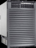
Introduction Detailed HP Integrity rx8620 Server Description Figure 1-14 HP Integrity rx8620 Server (Rear View) PCI OLR Fan PCI I/O Card Section Core I/O Card Rear OLR Fan AC Power Receptacle The PCI I/O card section, located toward the rear, is accessed by removing the top cover. The PCI OLR fan modules are located in front of the PCI cards. They are housed in plastic carriers. The cell boards are located on the right side of the product behind a removable side cover. Rack front doors are more often hinged on the left, which restricts the large cell board to slide out from the right. The two redundant core I/O cards are positioned vertically end-to-end at the rear of the chassis. The PCI card bulkhead connectors are located at the rear top. The 12 rear OLR fans attached external to the chassis house 120-mm exhaust fans. Redundant line cords attach to the AC power receptacles at the bottom rear. Two 20-amp cords are required to power the HP Integrity rx8620 Server. Two additional line cords provide redundancy. Access the system backplane by removing the left side cover. The system backplane hinges from the lower edge and is anchored at the top with a single large jack screw assembly. The SCSI ribbon cable assembly also routes across and fastens to the backside of the system backplane near the connectors that attach the core I/O boards. The blue deployment handles hinge outward to help lift and move the server into a rack. Chapter 1 29
-
 1
1 -
2
-
3
-
4
-
5
-
6
-
7
-
8
-
9
-
10
-
11
-
12
-
13
-
14
-
15
-
16
-
17
-
18
-
19
-
20
-
21
-
22
-
23
-
 24
24 -
 25
25 -
 26
26 -
 27
27 -
 28
28 -
 29
29 -
 30
30 -
 31
31 -
 32
32 -
 33
33 -
 34
34 -
35
-
36
-
37
-
38
-
39
-
40
-
41
-
42
-
43
-
44
-
45
-
46
-
47
-
48
-
49
-
50
-
51
-
52
-
53
-
54
-
55
-
56
-
57
-
58
-
59
-
60
-
61
-
62
-
63
-
64
-
65
-
66
-
67
-
68
-
69
-
70
-
71
-
72
-
73
-
74
-
75
-
76
-
77
-
78
-
79
-
80
-
81
-
82
-
83
-
84
-
85
-
86
-
87
-
88
-
89
-
90
-
91
-
92
-
93
-
94
-
95
-
96
 |
 |
