Intel D845PEBT2 Product Specification - Page 121
Port 80h POST Codes
 |
View all Intel D845PEBT2 manuals
Add to My Manuals
Save this manual to your list of manuals |
Page 121 highlights
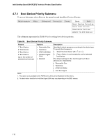
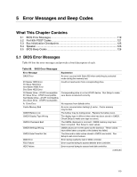
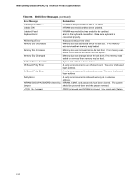
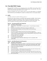
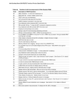
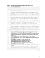
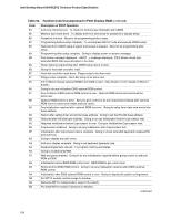
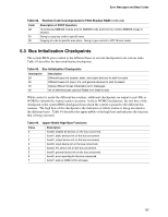
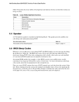
Error Messages and Beep Codes 5.2 Port 80h POST Codes During the POST, the BIOS generates diagnostic progress codes (POST-codes) to I/O port 80h. If the POST fails, execution stops and the last POST code generated is left at port 80h. This code is useful for determining the point where an error occurred. Displaying the POST-codes requires a PCI bus add-in card, often called a POST card. The POST card can decode the port and display the contents on a medium such as a seven-segment display. ✏ NOTE The POST card must be installed in PCI bus connector 1. The tables below offer descriptions of the POST codes generated by the BIOS. Table 90 defines the uncompressed INIT code checkpoints, Table 91 describes the boot block recovery code checkpoints, and Table 92 lists the runtime code uncompressed in F000 shadow RAM. Some codes are repeated in the tables because that code applies to more than one operation. Table 90. Uncompressed INIT Code Checkpoints Code D0 D1 D3 D4 D5 D6 D7 D8 D9 Description of POST Operation NMI is Disabled. Onboard KBC, RTC enabled (if present). Init code Checksum verification starting. Keyboard controller BAT test, CPU ID saved, and going to 4 GB flat mode. Do necessary chipset initialization, start memory refresh, and do memory sizing. Verify base memory. Init code to be copied to segment 0 and control to be transferred to segment 0. Control is in segment 0. To check recovery mode and verify main BIOS checksum. If either it is recovery mode or main BIOS checksum is bad, go to check point E0 for recovery else go to check point D7 for giving control to main BIOS. Find Main BIOS module in ROM image. Uncompress the main BIOS module. Copy main BIOS image to F000 shadow RAM and give control to main BIOS in F000 shadow RAM. Table 91. Boot Block Recovery Code Checkpoints Code E0 E8 E9 EA EB EC EF Description of POST Operation Onboard Floppy Controller (if any) is initialized. Compressed recovery code is uncompressed in F000:0000 in Shadow RAM and give control to recovery code in F000 Shadow RAM. Initialize interrupt vector tables, initialize system timer, initialize DMA controller and interrupt controller. Initialize extra (Intel Recovery) Module. Initialize floppy drive. Try to boot from floppy. If reading of boot sector is successful, give control to boot sector code. Booting from floppy failed, look for ATAPI (LS-120, Zip) devices. Try to boot from ATAPI. If reading of boot sector is successful, give control to boot sector code. Booting from floppy and ATAPI device failed. Give two beeps. Retry the booting procedure again (go to check point E9). 121
-
 1
1 -
2
-
3
-
4
-
5
-
6
-
7
-
8
-
9
-
10
-
11
-
12
-
13
-
14
-
15
-
16
-
17
-
18
-
19
-
20
-
21
-
22
-
23
-
24
-
25
-
26
-
27
-
28
-
29
-
30
-
31
-
32
-
33
-
34
-
35
-
36
-
37
-
38
-
39
-
40
-
41
-
42
-
43
-
44
-
45
-
46
-
47
-
48
-
49
-
50
-
51
-
52
-
53
-
54
-
55
-
56
-
57
-
58
-
59
-
60
-
61
-
62
-
63
-
64
-
65
-
66
-
67
-
68
-
69
-
70
-
71
-
72
-
73
-
74
-
75
-
76
-
77
-
78
-
79
-
80
-
81
-
82
-
83
-
84
-
85
-
86
-
87
-
88
-
89
-
90
-
91
-
92
-
93
-
94
-
95
-
96
-
97
-
98
-
99
-
100
-
101
-
102
-
103
-
104
-
105
-
106
-
107
-
108
-
109
-
110
-
111
-
112
-
113
-
114
-
115
-
 116
116 -
 117
117 -
 118
118 -
 119
119 -
 120
120 -
 121
121 -
 122
122 -
 123
123 -
 124
124 -
 125
125 -
 126
126 -
127
-
128
 |
 |