Intel D845PEBT2 Product Specification - Page 41
Power Connector, 16.2.2, Fan Connectors, CAUTION
 |
View all Intel D845PEBT2 manuals
Add to My Manuals
Save this manual to your list of manuals |
Page 41 highlights
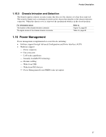
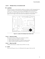
Product Description Resume on Ring enables telephony devices to access the computer when it is in a power-managed state. The method used depends on the type of telephony device (external or internal). ✏ NOTE The use of Resume on Ring and Wake from USB technologies from an ACPI state requires an operating system that provides full ACPI support. 1.16.2.1 Power Connector ATX12V-compliant power supplies can turn off the system power through system control. When an ACPI-enabled system receives the correct command, the power supply removes all non-standby voltages. When resuming from an AC power failure, the computer returns to the power state it was in before power was interrupted (on or off). The computer's response can be set using the Last Power State feature in the BIOS Setup program's Boot menu. For information about The power connector locations The power connector signal names The BIOS Setup program's Boot menu The ATX specification Refer to Figure 13, page 58 Table 30, page 59 and Table 33, page 60 Table 83, page 115 Section 1.4, page 17 1.16.2.2 Fan Connectors CAUTION The processor fan must be connected to the processor fan connector, not to a chassis fan connector. Connecting the processor fan to a chassis fan connector may result in onboard component damage that will halt fan operation. Table 9 summarizes the fan connector function/operation. Table 9. Fan Connector Function/Operation Connector Description Processor fan Front and rear chassis fans • +12 V DC connection for a processor fan or active fan heatsink. • Fan is on in the S0 or S1 state. Fan is off when the system is off or in the S3, S4, or S5 state. • Wired to a fan tachometer input of the hardware monitoring and fan control ASIC. • Closed-loop fan control that can adjust the fan speed or switch the fan on or off as needed. • +12 V DC connection for a system or chassis fan. • Fan is on in the S0 or S1 state. Fan is off when the system is off or in the S3, S4, or S5 state. • Wired to a fan tachometer input of the hardware monitoring and fan control ASIC. • Closed-loop fan control that can adjust the fan speed or switch the fan on or off as needed. For information about: The location of the fan connectors The signal names of the fan connectors The location of the fan connectors and sensors for thermal monitoring Refer to: Figure 13, page 58 Pages 59 and 60 Figure 9, page 36 41
-
 1
1 -
2
-
3
-
4
-
5
-
6
-
7
-
8
-
9
-
10
-
11
-
12
-
13
-
14
-
15
-
16
-
17
-
18
-
19
-
20
-
21
-
22
-
23
-
24
-
25
-
26
-
27
-
28
-
29
-
30
-
31
-
32
-
33
-
34
-
35
-
 36
36 -
 37
37 -
 38
38 -
 39
39 -
 40
40 -
 41
41 -
 42
42 -
 43
43 -
 44
44 -
 45
45 -
 46
46 -
47
-
48
-
49
-
50
-
51
-
52
-
53
-
54
-
55
-
56
-
57
-
58
-
59
-
60
-
61
-
62
-
63
-
64
-
65
-
66
-
67
-
68
-
69
-
70
-
71
-
72
-
73
-
74
-
75
-
76
-
77
-
78
-
79
-
80
-
81
-
82
-
83
-
84
-
85
-
86
-
87
-
88
-
89
-
90
-
91
-
92
-
93
-
94
-
95
-
96
-
97
-
98
-
99
-
100
-
101
-
102
-
103
-
104
-
105
-
106
-
107
-
108
-
109
-
110
-
111
-
112
-
113
-
114
-
115
-
116
-
117
-
118
-
119
-
120
-
121
-
122
-
123
-
124
-
125
-
126
-
127
-
128
 |
 |