Intel D845PEBT2 Product Specification - Page 73
BIOS Setup Configuration Jumper Block
 |
View all Intel D845PEBT2 manuals
Add to My Manuals
Save this manual to your list of manuals |
Page 73 highlights
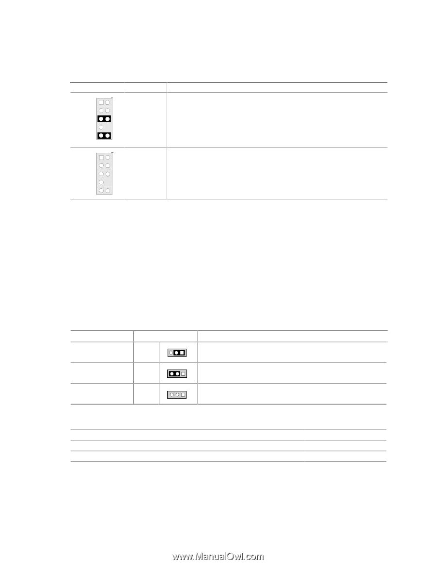
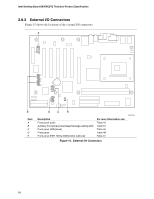
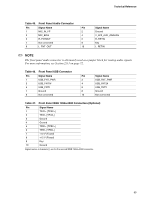
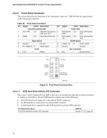
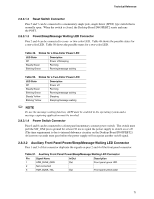
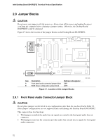
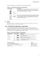
Technical Reference Table 52 describes the two configurations of this connector/jumper block. Table 52. Front Panel Audio Connector or Jumper Block Jumper Setting 1 2 3 4 5 6 5 and 6 7 9 10 9 and 10 Configuration Front out signals if 6-channel audio (line out signals if 2-channel audio) are routed to the back panel line out connector. The back panel audio line out connector is shown in Figure 11 on page 52. Mic in and front out signals if 6-channel audio (line out signals if 2-channel 1 2 No jumpers audio) are available for connection to front panel audio connectors. Table 3 4 installed 45 on page 69 lists the names of the signals available on this connector 5 6 when no jumpers are installed. 7 9 10 ✏ NOTE When the jumpers are removed and this connector is used for front panel audio, the back panel audio line out and mic in connectors are disabled. 2.9.2 BIOS Setup Configuration Jumper Block The 3-pin jumper block determines the BIOS Setup program's mode. Table 53 describes the jumper settings for the three modes: normal, configure, and recovery. When the jumper is set to configuration mode and the computer is powered-up, the BIOS compares the processor version and the microcode version in the BIOS and reports if the two match. Table 53. BIOS Setup Configuration Jumper Settings Function/Mode Normal Jumper Setting 1-2 3 1 Configuration The BIOS uses current configuration information and passwords for booting. Configure 2-3 3 After the POST runs, Setup runs automatically. The 1 maintenance menu is displayed. Recovery None 3 The BIOS attempts to recover the BIOS configuration. A 1 recovery diskette is required. For information about How to access the BIOS Setup program The maintenance menu of the BIOS Setup program BIOS recovery Refer to Section 4.1, page 97 Section 4, page 97 Section 3.7, page 92 73
-
 1
1 -
2
-
3
-
4
-
5
-
6
-
7
-
8
-
9
-
10
-
11
-
12
-
13
-
14
-
15
-
16
-
17
-
18
-
19
-
20
-
21
-
22
-
23
-
24
-
25
-
26
-
27
-
28
-
29
-
30
-
31
-
32
-
33
-
34
-
35
-
36
-
37
-
38
-
39
-
40
-
41
-
42
-
43
-
44
-
45
-
46
-
47
-
48
-
49
-
50
-
51
-
52
-
53
-
54
-
55
-
56
-
57
-
58
-
59
-
60
-
61
-
62
-
63
-
64
-
65
-
66
-
67
-
 68
68 -
 69
69 -
 70
70 -
 71
71 -
 72
72 -
 73
73 -
 74
74 -
 75
75 -
 76
76 -
 77
77 -
 78
78 -
79
-
80
-
81
-
82
-
83
-
84
-
85
-
86
-
87
-
88
-
89
-
90
-
91
-
92
-
93
-
94
-
95
-
96
-
97
-
98
-
99
-
100
-
101
-
102
-
103
-
104
-
105
-
106
-
107
-
108
-
109
-
110
-
111
-
112
-
113
-
114
-
115
-
116
-
117
-
118
-
119
-
120
-
121
-
122
-
123
-
124
-
125
-
126
-
127
-
128
 |
 |