Intel D845PEBT2 Product Specification - Page 65
Table 39., ATAPI-Style CD-ROM Connector, Table 40., Diskette Drive Connector
 |
View all Intel D845PEBT2 manuals
Add to My Manuals
Save this manual to your list of manuals |
Page 65 highlights
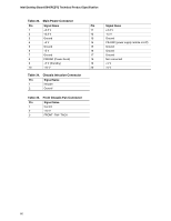
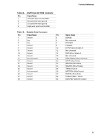
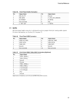
Technical Reference Table 39. ATAPI-Style CD-ROM Connector Pin Signal Name 1 Left audio input from CD-ROM 2 CD audio differential ground 3 CD audio differential ground 4 Right audio input from CD-ROM Table 40. Diskette Drive Connector Pin Signal Name Pin 1 Ground 2 3 Key 4 5 Key 6 7 Ground 8 9 Ground 10 11 Ground 12 13 Ground 14 15 Ground 16 17 Not connected 18 19 Ground 20 21 Ground 22 23 Ground 24 25 Ground 26 27 Not connected 28 29 Ground 30 31 Ground 32 33 Ground 34 Signal Name DENSEL Not connected DRVDEN1 FDINDX# MTR0# (Motor Enable A) Not connected DS0# (Drive Select A) Not connected DIR# (Stepper Motor Direction) STEP# (Step Pulse) WDATA# (Write Data) WGATE# (Write Enable) TRK0# (Track 0) WRTPRT# (Write Protect) RDATA# (Read Data) HDSEL# (Side 1 Select) DSKCHG# (Diskette Change) 65
-
 1
1 -
2
-
3
-
4
-
5
-
6
-
7
-
8
-
9
-
10
-
11
-
12
-
13
-
14
-
15
-
16
-
17
-
18
-
19
-
20
-
21
-
22
-
23
-
24
-
25
-
26
-
27
-
28
-
29
-
30
-
31
-
32
-
33
-
34
-
35
-
36
-
37
-
38
-
39
-
40
-
41
-
42
-
43
-
44
-
45
-
46
-
47
-
48
-
49
-
50
-
51
-
52
-
53
-
54
-
55
-
56
-
57
-
58
-
59
-
 60
60 -
 61
61 -
 62
62 -
 63
63 -
 64
64 -
 65
65 -
 66
66 -
 67
67 -
 68
68 -
 69
69 -
 70
70 -
71
-
72
-
73
-
74
-
75
-
76
-
77
-
78
-
79
-
80
-
81
-
82
-
83
-
84
-
85
-
86
-
87
-
88
-
89
-
90
-
91
-
92
-
93
-
94
-
95
-
96
-
97
-
98
-
99
-
100
-
101
-
102
-
103
-
104
-
105
-
106
-
107
-
108
-
109
-
110
-
111
-
112
-
113
-
114
-
115
-
116
-
117
-
118
-
119
-
120
-
121
-
122
-
123
-
124
-
125
-
126
-
127
-
128
 |
 |