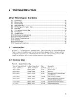
Intel D845PEBT2 Product Specification - Page 50
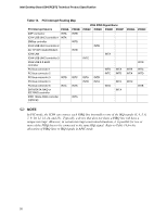
Table 15., PCI Interrupt Routing Map
 |
View all Intel D845PEBT2 manuals
Add to My Manuals
Save this manual to your list of manuals |
Page 50 highlights
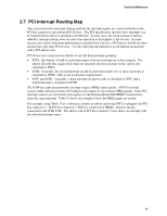
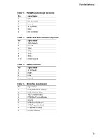
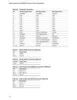
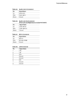
Intel Desktop Board D845PEBT2 Technical Product Specification Table 15. PCI Interrupt Routing Map PCI Interrupt Source PIRQA AGP connector INTA ICH4 USB UHCI controller 1 INTA SMBus controller ICH4 USB UHCI controller 2 AC '97 ICH4 Audio/Modem ICH4 LAN ICH4 USB UHCI controller 3 ICH4 USB 2.0 EHCI controller PCI bus connector 1 PCI bus connector 2 PCI bus connector 3 INTD PCI bus connector 4 PCI bus connector 5 INTC SATA/SATA RAID or IDE RAID controller IEEE 1394a-2000 controller (optional) PIRQB INTB INTB INTB INTC INTA INTA ICH4 PIRQ Signal Name PIRQC PIRQD PIRQE PIRQF INTB INTC INTA INTA INTB INTB INTA INTD INTC INTD INTA INTB INTC INTA PIRQG INTB INTA INTD PIRQH INTD INTC INTD INTB ✏ NOTE In PIC mode, the ICH4 can connect each PIRQ line internally to one of the IRQ signals (3, 4, 5, 6, 7, 9, 10, 11, 12, 14, and 15). Typically, a device that does not share a PIRQ line will have a unique interrupt. However, in certain interrupt-constrained situations, it is possible for two or more of the PIRQ lines to be connected to the same IRQ signal. Refer to Table 14 for the allocation of PIRQ lines to IRQ signals in APIC mode. 50
-
 1
1 -
2
-
3
-
4
-
5
-
6
-
7
-
8
-
9
-
10
-
11
-
12
-
13
-
14
-
15
-
16
-
17
-
18
-
19
-
20
-
21
-
22
-
23
-
24
-
25
-
26
-
27
-
28
-
29
-
30
-
31
-
32
-
33
-
34
-
35
-
36
-
37
-
38
-
39
-
40
-
41
-
42
-
43
-
44
-
 45
45 -
 46
46 -
 47
47 -
 48
48 -
 49
49 -
 50
50 -
 51
51 -
 52
52 -
 53
53 -
 54
54 -
 55
55 -
56
-
57
-
58
-
59
-
60
-
61
-
62
-
63
-
64
-
65
-
66
-
67
-
68
-
69
-
70
-
71
-
72
-
73
-
74
-
75
-
76
-
77
-
78
-
79
-
80
-
81
-
82
-
83
-
84
-
85
-
86
-
87
-
88
-
89
-
90
-
91
-
92
-
93
-
94
-
95
-
96
-
97
-
98
-
99
-
100
-
101
-
102
-
103
-
104
-
105
-
106
-
107
-
108
-
109
-
110
-
111
-
112
-
113
-
114
-
115
-
116
-
117
-
118
-
119
-
120
-
121
-
122
-
123
-
124
-
125
-
126
-
127
-
128
 |
 |