Intel D845PEBT2 Product Specification - Page 125
Bus Initialization Checkpoints
 |
View all Intel D845PEBT2 manuals
Add to My Manuals
Save this manual to your list of manuals |
Page 125 highlights
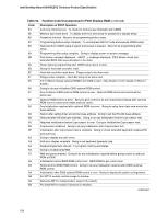
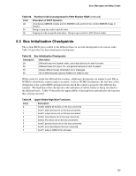
Error Messages and Beep Codes Table 92. Runtime Code Uncompressed in F000 Shadow RAM (continued) Code AE B1 00 Description of POST Operation Uncompress SMBIOS module and init SMBIOS code and form the runtime SMBIOS image in shadow. Going to copy any code to specific area. Copying of code to specific area done. Going to give control to INT-19 boot loader. 5.3 Bus Initialization Checkpoints The system BIOS gives control to the different buses at several checkpoints to do various tasks. Table 93 describes the bus initialization checkpoints. Table 93. Bus Initialization Checkpoints Checkpoint Description 2A Different buses init (system, static, and output devices) to start if present. 38 Different buses init (input, IPL, and general devices) to start if present. 39 Display different buses initialization error messages. 95 Init of different buses optional ROMs from C800 to start. While control is inside the different bus routines, additional checkpoints are output to port 80h as WORD to identify the routines under execution. In these WORD checkpoints, the low byte of the checkpoint is the system BIOS checkpoint from which the control is passed to the different bus routines. The high byte of the checkpoint is the indication of which routine is being executed in the different buses. Table 94 describes the upper nibble of the high byte and indicates the function that is being executed. Table 94. Upper Nibble High Byte Functions Value Description 0 func#0, disable all devices on the bus concerned. 1 func#1, static devices init on the bus concerned. 2 func#2, output device init on the bus concerned. 3 func#3, input device init on the bus concerned. 4 func#4, IPL device init on the bus concerned. 5 func#5, general device init on the bus concerned. 6 func#6, error reporting for the bus concerned. 7 func#7, add-on ROM init for all buses. 125
-
 1
1 -
2
-
3
-
4
-
5
-
6
-
7
-
8
-
9
-
10
-
11
-
12
-
13
-
14
-
15
-
16
-
17
-
18
-
19
-
20
-
21
-
22
-
23
-
24
-
25
-
26
-
27
-
28
-
29
-
30
-
31
-
32
-
33
-
34
-
35
-
36
-
37
-
38
-
39
-
40
-
41
-
42
-
43
-
44
-
45
-
46
-
47
-
48
-
49
-
50
-
51
-
52
-
53
-
54
-
55
-
56
-
57
-
58
-
59
-
60
-
61
-
62
-
63
-
64
-
65
-
66
-
67
-
68
-
69
-
70
-
71
-
72
-
73
-
74
-
75
-
76
-
77
-
78
-
79
-
80
-
81
-
82
-
83
-
84
-
85
-
86
-
87
-
88
-
89
-
90
-
91
-
92
-
93
-
94
-
95
-
96
-
97
-
98
-
99
-
100
-
101
-
102
-
103
-
104
-
105
-
106
-
107
-
108
-
109
-
110
-
111
-
112
-
113
-
114
-
115
-
116
-
117
-
118
-
119
-
 120
120 -
 121
121 -
 122
122 -
 123
123 -
 124
124 -
 125
125 -
 126
126 -
 127
127 -
 128
128
 |
 |