Intel D845PEBT2 Product Specification - Page 49
PCI Interrupt Routing Map
 |
View all Intel D845PEBT2 manuals
Add to My Manuals
Save this manual to your list of manuals |
Page 49 highlights
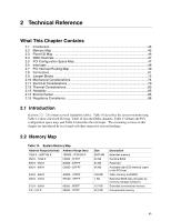
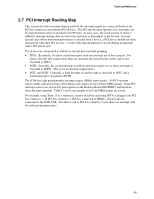
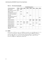
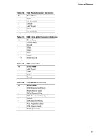
Technical Reference 2.7 PCI Interrupt Routing Map This section describes interrupt sharing and how the interrupt signals are connected between the PCI bus connectors and onboard PCI devices. The PCI specification specifies how interrupts can be shared between devices attached to the PCI bus. In most cases, the small amount of latency added by interrupt sharing does not affect the operation or throughput of the devices. In some special cases where maximum performance is needed from a device, a PCI device should not share an interrupt with other PCI devices. Use the following information to avoid sharing an interrupt with a PCI add-in card. PCI devices are categorized as follows to specify their interrupt grouping: • INTA: By default, all add-in cards that require only one interrupt are in this category. For almost all cards that require more than one interrupt, the first interrupt on the card is also classified as INTA. • INTB: Generally, the second interrupt on add-in cards that require two or more interrupts is classified as INTB. (This is not an absolute requirement.) • INTC and INTD: Generally, a third interrupt on add-in cards is classified as INTC and a fourth interrupt is classified as INTD. The ICH4 has eight programmable interrupt request (PIRQ) input signals. All PCI interrupt sources either onboard or from a PCI add-in card connect to one of these PIRQ signals. Some PCI interrupt sources are electrically tied together on the Desktop Board D845PEBT2 and therefore share the same interrupt. Table 15 shows an example of how the PIRQ signals are routed. For example, using Table 15 as a reference, assume an add-in card using INTA is plugged into PCI bus connector 3. In PCI bus connector 3, INTA is connected to PIRQC, which is already connected to the ICH4 USB. The add-in card in PCI bus connector 3 now shares an interrupt with the onboard interrupt source. 49
-
 1
1 -
2
-
3
-
4
-
5
-
6
-
7
-
8
-
9
-
10
-
11
-
12
-
13
-
14
-
15
-
16
-
17
-
18
-
19
-
20
-
21
-
22
-
23
-
24
-
25
-
26
-
27
-
28
-
29
-
30
-
31
-
32
-
33
-
34
-
35
-
36
-
37
-
38
-
39
-
40
-
41
-
42
-
43
-
 44
44 -
 45
45 -
 46
46 -
 47
47 -
 48
48 -
 49
49 -
 50
50 -
 51
51 -
 52
52 -
 53
53 -
 54
54 -
55
-
56
-
57
-
58
-
59
-
60
-
61
-
62
-
63
-
64
-
65
-
66
-
67
-
68
-
69
-
70
-
71
-
72
-
73
-
74
-
75
-
76
-
77
-
78
-
79
-
80
-
81
-
82
-
83
-
84
-
85
-
86
-
87
-
88
-
89
-
90
-
91
-
92
-
93
-
94
-
95
-
96
-
97
-
98
-
99
-
100
-
101
-
102
-
103
-
104
-
105
-
106
-
107
-
108
-
109
-
110
-
111
-
112
-
113
-
114
-
115
-
116
-
117
-
118
-
119
-
120
-
121
-
122
-
123
-
124
-
125
-
126
-
127
-
128
 |
 |