JVC GY-DV500U GY-DV500 User Manual - PDF (4,089KB) - Page 25
Indications in Viewfinder - gy dv500 error messages
 |
View all JVC GY-DV500U manuals
Add to My Manuals
Save this manual to your list of manuals |
Page 25 highlights
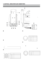
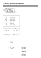
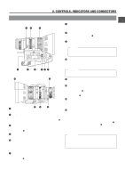
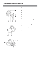
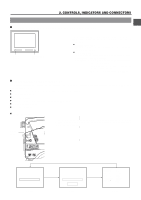
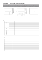
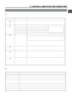
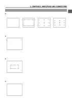
2. CONTROLS, INDICATORS AND CONNECTORS 2-9 Indications in Viewfinder Ⅲ WARNING LED INDICATORS INSIDE THE VIEWFINDER BATT BATT Lamp REC ALARM REC/ALARM Lamp The viewfinder has two LED indicators below the screen. These LEDs light or blink to indicate the present status of the camera or the VCR. ● [BATT] battery lamp This lights red when the battery voltage becomes too low for operating the camera. ● REC/ALARM lamp This lights or blinks green under the following circumstances. Steady green : During recording. Blinks green : • While the GY-DV500 switches from record- pause to recording. • Immediately before the tape is running out or when it has run out. • When an error occurs in the GY-DV500. Ⅲ VIEWFINDER SCREEN DISPLAY The following indications are displayed on the viewfinder screen. (However, this information is not displayed while the VCR section is playing back a tape.) Ⅲ Status screens (screens for use in checking the current camera settings) Ⅲ Alarm message display Ⅲ Safety zone display Ⅲ Setting screen (screen for use in the camera and VCR setup) Ⅲ Auto white balance display Ⅲ Shutter speed display Ⅲ Status Screens Press the STATUS button during normal screen display to show one of the status screens in the viewfinder. One of the three status screens will be displayed every time the button is pressed. STATUS button FILTER 1 3200k 2 5600k 3 5600k+ND SHUTTER STATUS MENU ALARM MONITOR AUTO IRIS FULL AUTO BLACK BACK L NORMAL SPOT L STRETCH NORMAL COMPRESS LOLUX PRST A B ON KNEE OFF AUTO BARS CAM HML SAVE STBY VTR GAIN OUTPUT WHT.BAL NG POWER ON OFF OPERATE/WARNING RESET MONITOR SELECT CH-1 AUDIO CH-2 LEVEL LIGHT ON OFF COUNTER CTL TC UB ACCU - FOCUS G F I SD B Status 0 F5 . 6 STBY ACCU - FOCUS G F CH1 CH2 < 60 I SD B M 09 9 1 2 . 4V Status 1 SCENE F I LE WH I TE BA L F I L TER SHUT TER GA I N I R I S LEVEL I R I S DETECT FUL L AUTO REC T I ME A A 3 . 2K 1 / 1000 6dB NORMA L NORMA L OF F
-
 1
1 -
2
-
3
-
4
-
5
-
6
-
7
-
8
-
9
-
10
-
11
-
12
-
13
-
14
-
15
-
16
-
17
-
18
-
19
-
 20
20 -
 21
21 -
 22
22 -
 23
23 -
 24
24 -
 25
25 -
 26
26 -
 27
27 -
 28
28 -
 29
29 -
 30
30 -
31
-
32
-
33
-
34
-
35
-
36
-
37
-
38
-
39
-
40
-
41
-
42
-
43
-
44
-
45
-
46
-
47
-
48
-
49
-
50
-
51
-
52
-
53
-
54
-
55
-
56
-
57
-
58
-
59
-
60
-
61
-
62
-
63
-
64
-
65
-
66
-
67
-
68
-
69
-
70
-
71
-
72
-
73
-
74
-
75
-
76
-
77
-
78
-
79
-
80
-
81
-
82
-
83
-
84
-
85
-
86
-
87
-
88
-
89
-
90
-
91
-
92
-
93
-
94
-
95
-
96
 |
 |
