JVC GY-DV500U GY-DV500 User Manual - PDF (4,089KB) - Page 77
SETUP Screen
 |
View all JVC GY-DV500U manuals
Add to My Manuals
Save this manual to your list of manuals |
Page 77 highlights
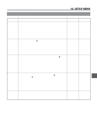
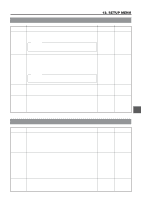
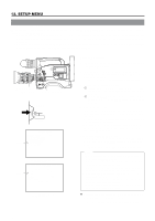
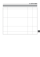
12-10 SETUP Screen 12. SETUP MENU Item H PHASE Function, Operation Variation Range Initial Setting For adjusting the horizontal phase of the unit in relation to the signal 0 128 (external sync signal) input through the SYNC IN connector on the left to side of the unit. 256 Delaying the horizontal phase of the unit in relation to the external sync signal . Increase the number Speeding up the horizontal phase of the unit in relation to the external sync signal . Decrease the number * Adjustment is not possible if the external sync signal is not input. Possible values are indicated by ***. SC PHASE For adjusting the sub-carrier (SC) of the unit in relation to the signal 0 (external sync signal) input through the SYNC IN connector on the left to 128 side of the unit. 256 Rotating the sub-carrier clockwise in relation to the external sync signal Increase the number Rotating the sub-carrier anticlockwise in relation to the external sync signal Decrease the number * Adjustment is not possible if the external sync signal is not input. Possible values are indicated by ***. The phase will change when the power is turned on/off. The SC phase must be adjusted each time the power is turned on. CAM MIC +48V To set whether or not 48V voltage should be applied to the MIC IN connector ON ON on the front section. OFF ON 48V applied. OFF 48V not applied. PAGE BACK The CAMERA MENU returns when the SHUTTER dial is pressed with - - the cursor at this position. 77
-
 1
1 -
2
-
3
-
4
-
5
-
6
-
7
-
8
-
9
-
10
-
11
-
12
-
13
-
14
-
15
-
16
-
17
-
18
-
19
-
20
-
21
-
22
-
23
-
24
-
25
-
26
-
27
-
28
-
29
-
30
-
31
-
32
-
33
-
34
-
35
-
36
-
37
-
38
-
39
-
40
-
41
-
42
-
43
-
44
-
45
-
46
-
47
-
48
-
49
-
50
-
51
-
52
-
53
-
54
-
55
-
56
-
57
-
58
-
59
-
60
-
61
-
62
-
63
-
64
-
65
-
66
-
67
-
68
-
69
-
70
-
71
-
 72
72 -
 73
73 -
 74
74 -
 75
75 -
 76
76 -
 77
77 -
 78
78 -
 79
79 -
 80
80 -
 81
81 -
 82
82 -
83
-
84
-
85
-
86
-
87
-
88
-
89
-
90
-
91
-
92
-
93
-
94
-
95
-
96
 |
 |
