JVC GY-DV500U GY-DV500 User Manual - PDF (4,089KB) - Page 64
Using External Components
 |
View all JVC GY-DV500U manuals
Add to My Manuals
Save this manual to your list of manuals |
Page 64 highlights
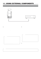
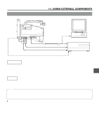
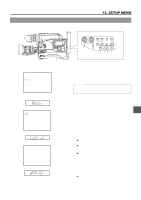
11. USING EXTERNAL COMPONENTS 11-1 Connecting a Video Component with DV Connector Rear section of GY-DV500 EARPHONE DV CH-1 AUDIO IN CH-2 LINE MIC LINE MIC DC INPUT +48V ON +48V ON TALLY DC OUTPUT DV connector Video component with DV Connector DV connector DV cable When connecting the GY-DV500 to a non-linear editing controller or other component with DV connector, be sure to observe the following procedure. Ⅲ When using the GY-DV500 as playback component 1. Turn ON both units. 2. Confirm that the VCR Setup Menu item No.126 INPUT SELECT is set to "CAMERA"(cA). * If set to "IEEE1394", set it to "CAMERA" and then turn ON the power again. 3. Insert the videocassette. 4. Connect the DV cable. Memo: When the GY-DV500 is controlled through the DV connector, set the VCR Setup Menu item No.050 REMOTE SELECT to "IEEE1394". However, the following functions may not work depending on the component that the GY-DV500 is connected to. • REC • FF (FWD search is possible) • REW (REV search is possible) Ⅲ When using the GY-DV500 as recording component 1. Turn ON both units. 2. Set the VCR Setup Menu item No.126 INPUT SELECT to "IEEE1394"(iE). 3. Insert the videocassette. 4. Connect the DV cable. Memo: • When recording while controlling the GY-DV500 through the DV connector from another component with DV connector, set the VCR Setup Menu item No.050 REMOTE SELECT to "IEEE1394". In this case, it takes approximately 2 to 3 seconds before recording starts on the GY-DV500. • When video is input through the DV connector, the EE picture is not displayed in the viewfinder. Ⅲ When the GY-DV500 is used as camera, and a backup recording is made on another component via the DV connector, set the VCR Setup Menu item No.126 INPUT SELECT to "CAMERA". Note: If the above procedure is not performed correctly, the playback picture may be disturbed or the sound may fall out. If this happens, redo the connection by performing steps 1. to 4. described above. 64
-
 1
1 -
2
-
3
-
4
-
5
-
6
-
7
-
8
-
9
-
10
-
11
-
12
-
13
-
14
-
15
-
16
-
17
-
18
-
19
-
20
-
21
-
22
-
23
-
24
-
25
-
26
-
27
-
28
-
29
-
30
-
31
-
32
-
33
-
34
-
35
-
36
-
37
-
38
-
39
-
40
-
41
-
42
-
43
-
44
-
45
-
46
-
47
-
48
-
49
-
50
-
51
-
52
-
53
-
54
-
55
-
56
-
57
-
58
-
 59
59 -
 60
60 -
 61
61 -
 62
62 -
 63
63 -
 64
64 -
 65
65 -
 66
66 -
 67
67 -
 68
68 -
 69
69 -
70
-
71
-
72
-
73
-
74
-
75
-
76
-
77
-
78
-
79
-
80
-
81
-
82
-
83
-
84
-
85
-
86
-
87
-
88
-
89
-
90
-
91
-
92
-
93
-
94
-
95
-
96
 |
 |
