JVC GY-DV500U GY-DV500 User Manual - PDF (4,089KB) - Page 63
Outputting S.S.F. Data, Writing S.S.F. Data to Tape - - camcorder
 |
View all JVC GY-DV500U manuals
Add to My Manuals
Save this manual to your list of manuals |
Page 63 highlights
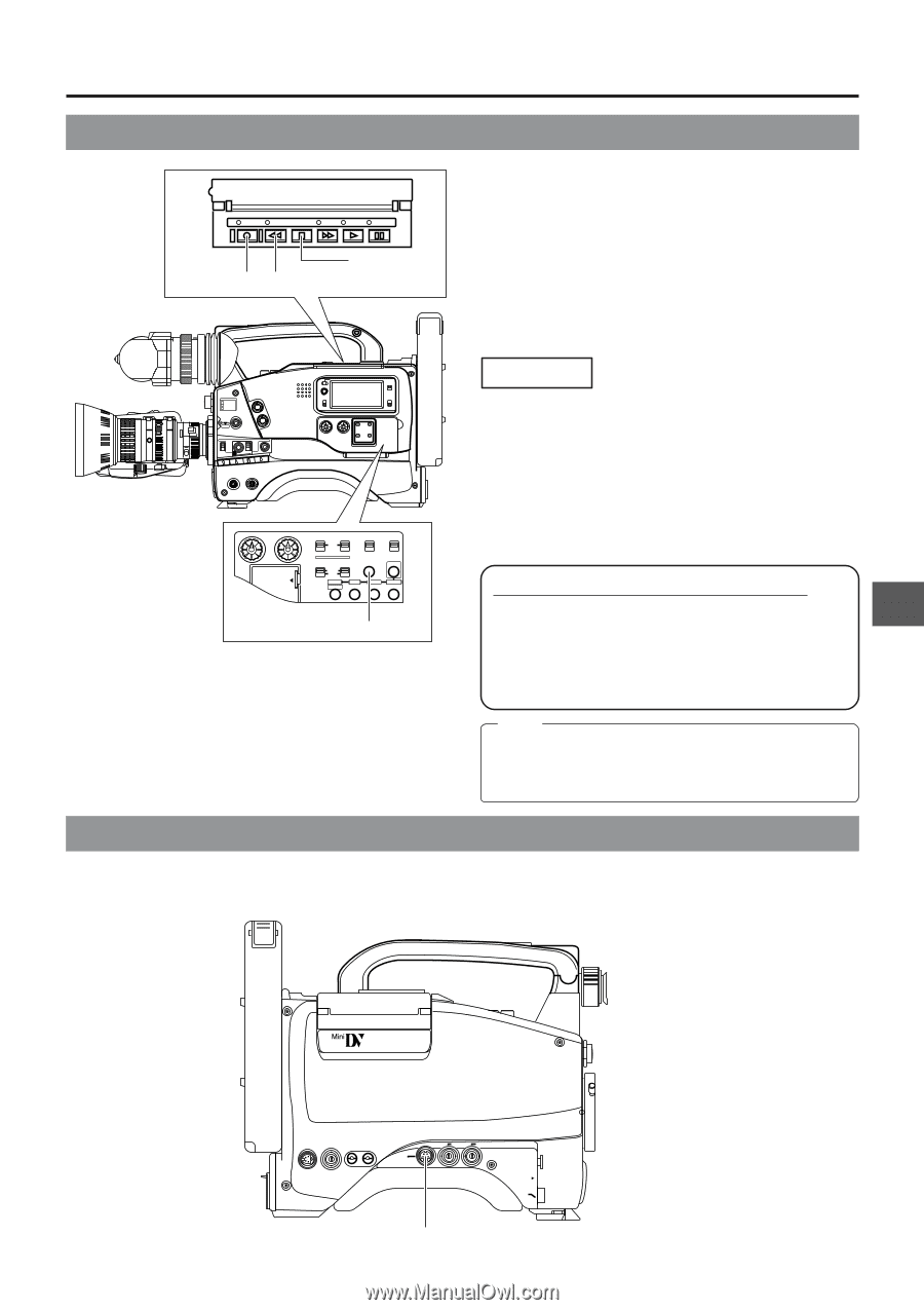
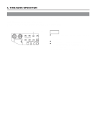
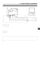
10. S.S.F. (Super Scene Finder) FUNCTION 10-5 Writing S.S.F. Data to Tape LOG REW STOP FF PLAY STILL 1. STOP button 2. LOG button 2. REW button S.S.F. data stored in the unitís memory can be written to the beginning of tape. Precautions when writing S.S.F. data When S.S.F. data stored in the memory of the GY-DV500 is written to the beginning of the rewound tape, approximately 5 seconds of recorded video and/or sound will be erased at the beginning. In the case of important recordings, leave 5 seconds or more of the tape unrecorded before starting recording. FILTER 1 3200k 2 5600k 3 5600k+ND SHUTTER STATUS MENU ALARM MONITOR AUTO IRIS FULL AUTO BLACK BACK L NORMAL SPOT L STRETCH NORMAL COMPRESS LOLUX PRST A B ON KNEE OFF AUTO BARS CAM HML SAVE STBY VTR GAIN OUTPUT WHT.BAL NG POWER ON OFF OPERATE/WARNING RESET MONITOR SELECT CH-1 AUDIO CH-2 LEVEL LIGHT ON OFF COUNTER CTL TC UB CH-1 AUDIO LEVEL CH-2 LITHIUM BATT. CH-1 CH-2 TC GENERATOR AUTO MANUAL PRESET REGEN AUDIO SELECT FREE REC AUDIO INPUT CH-1 CH-2 CONTINUE MENU FRONT REAR GROUP HOLD ITEM SELECT DATA SET SHIFT ADVANCE PRESET CONTINUE button Operation 1. Press the STOP button to enter the stop mode. 2. Press the REW button while the LOG button is kept pressed. • The REW indicator blinks during tape transport in the writing position. The LOG indicator lights while S.S.F. data are being written to the tape. • When writing to the tape is completed, the LOG indicator goes out. About the Scene End Cue Up Function Ⅲ When the CONTINUE button is pressed while the LOG button is kept pressed in the stop mode, the tape winds to the S.S.F. data's last OUT point, after which the unit enters the record-pause mode. (Scene End Cue Up) The FF button's LED blinks during the Scene End Cue Up mode. Note: Once a tape with recorded S.S.F. data is ejected and then reinserted again, the previous data will be erased if new S.S.F. data are recorded on the tape. 10-6 Outputting S.S.F. Data PUSH The S.S.F. data stored in the unit's memory can be output by RS-232C control via the VTR REMOTE connector. For how to connect, see "Connecting a PC" on page 65. DV CAMCORDER GY-DV500 Y/C OUT MONITOR OUT LINE OUT CH-1 CH-2 VTR REMOTE SYNC IN TEST OUT MIC IN LENS VTR REMOTE connector 63
-
 1
1 -
2
-
3
-
4
-
5
-
6
-
7
-
8
-
9
-
10
-
11
-
12
-
13
-
14
-
15
-
16
-
17
-
18
-
19
-
20
-
21
-
22
-
23
-
24
-
25
-
26
-
27
-
28
-
29
-
30
-
31
-
32
-
33
-
34
-
35
-
36
-
37
-
38
-
39
-
40
-
41
-
42
-
43
-
44
-
45
-
46
-
47
-
48
-
49
-
50
-
51
-
52
-
53
-
54
-
55
-
56
-
57
-
 58
58 -
 59
59 -
 60
60 -
 61
61 -
 62
62 -
 63
63 -
 64
64 -
 65
65 -
 66
66 -
 67
67 -
 68
68 -
69
-
70
-
71
-
72
-
73
-
74
-
75
-
76
-
77
-
78
-
79
-
80
-
81
-
82
-
83
-
84
-
85
-
86
-
87
-
88
-
89
-
90
-
91
-
92
-
93
-
94
-
95
-
96
 |
 |