JVC GY-DV500U GY-DV500 User Manual - PDF (4,089KB) - Page 68
Vcr Setup Menu Contents
 |
View all JVC GY-DV500U manuals
Add to My Manuals
Save this manual to your list of manuals |
Page 68 highlights
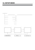
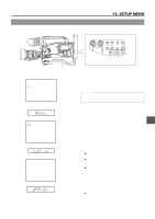
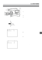
12. SETUP MENU 12-1 VCR Setup Menu (Cont'd) VCR SETUP MENU CONTENTS Group SERVO /SYSTEM VIDEO AUDIO Item Setting Value Upper row: Viewfinder display Lower row: Counter display indication 050: REMOTE SELECT LOCAL IEEE1394 RS232C rnSL Lc IE 23 Contents Factory Setting Selection of the method for remote control of the VCR. LOCAL : Choose this setting when the VCR should be controlled using the operation buttons on the GY-DV500 only. IEEE1394 : Choose this setting when the VCR should be remote controlled from a DV connector equipped video component connected to the DV connector on the rear section of the GY-DV500. RS232C : Choose this setting for control by means of the VCR remote control signal from the VTR REMOTE connector on the GY-DV500. * The operation buttons on the GY-DV500 remain effective even when set to IEEE1394 or RS232C. LOCAL 082: BACK TALLY MODE rtMd OFF ON BLINK oF on bL Selection of the lighting pattern of the BACK TALLY lamp on the rear section during recording. OFF : The lamp is always off. ON : The lamp lights during recording. It remains off until the VTR trigger button is pressed to start the recording. BLINK : The lamp lights during recording. It blinks when the VTR trigger button is pressed to start the recording. BLINK 126: INPUT SELECT vld CAMERA IEEE1394 cA IEEE1394 Selection of the input video signal. Settings cannot be changed during recording. CAMERA : Camera image is input. IEEE1394 : The image from the DV connector equipped video component connected to the DV connector on the rear section is input. CAMERA 244: LOW CUT LctF OFF CH1 CH2 CH1 & CH2 oF 01 02 on To select whether or not the low frequencies of the audio signal from the audio input connectors are cut. Set to ON to reduce the wind noise of the microphone. OFF : The CH1 and CH2 low frequencies are not cut. CH1 : Only the low frequencies of the audio signal input to the CH1 channel are cut. CH2 : Only the low frequencies of the audio signal input to the CH2 channel are cut. CH1& CH2 :The low frequencies are cut for both CH1 and CH2. OFF 245: SAMPLING RATE snPL 32K To select the sampling rate for digital PCM audio recording. 48K 48K 32K : Digital recording occurs with 12-bit, 32 kHz sampling 32 48K : Digital recording occurs with 16-bit 48 kHz 48 sampling. * The DV format offers recording tracks for up to 4 channel when recording using 12-bit, 32 kHz sampling. The GY-DV500 records two of these tracks. The GY-DV500 does not allow after-recording. 246: FRONT VOLUME ENABLE FruL DISABLE ENABLE oF on To select whether or not the front section recording level control should be operative. The front section recording level control only affects the audio signal recorded on CH1. DISABLE : Use of the front section recording level control is disabled. ENABLE : Use of the front section recording level control is enabled. * The CH-1 recording level control on the side section works regardless of the setting. ENABLE 68
-
 1
1 -
2
-
3
-
4
-
5
-
6
-
7
-
8
-
9
-
10
-
11
-
12
-
13
-
14
-
15
-
16
-
17
-
18
-
19
-
20
-
21
-
22
-
23
-
24
-
25
-
26
-
27
-
28
-
29
-
30
-
31
-
32
-
33
-
34
-
35
-
36
-
37
-
38
-
39
-
40
-
41
-
42
-
43
-
44
-
45
-
46
-
47
-
48
-
49
-
50
-
51
-
52
-
53
-
54
-
55
-
56
-
57
-
58
-
59
-
60
-
61
-
62
-
 63
63 -
 64
64 -
 65
65 -
 66
66 -
 67
67 -
 68
68 -
 69
69 -
 70
70 -
 71
71 -
 72
72 -
 73
73 -
74
-
75
-
76
-
77
-
78
-
79
-
80
-
81
-
82
-
83
-
84
-
85
-
86
-
87
-
88
-
89
-
90
-
91
-
92
-
93
-
94
-
95
-
96
 |
 |