JVC GY-DV500U GY-DV500 User Manual - PDF (4,089KB) - Page 33
Attaching the Tripod Base provided
 |
View all JVC GY-DV500U manuals
Add to My Manuals
Save this manual to your list of manuals |
Page 33 highlights
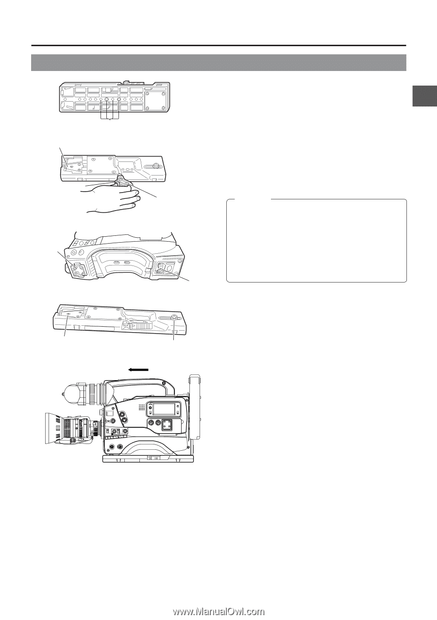
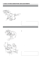
3. BASIC SYSTEM CONNECTIONS AND ADJUSTMENTS 3-6 Attaching the Tripod Base (provided) 1. Tripod mounting holes Front mount clip 2. Safety lever 4. Front base mount 2. Lock lever 3. Rear base mount Use the provided tripod base to place the camera on a tripod. 1. Attach the tripod base on the tripod by using the hole that balances the unit most optimally. 2. While pushing the safety lever, pull the lock lever toward the front until the front mount clip clicks into place. 3. Place the unit on the tripod base by aligning the rear base mount of the unit with the pin on the tripod base. 4. Push the unit from the upward direction and slide it toward the front so that the front base mount of the unit is locked by the front mount clip of the tripod base as it clicks into place. CAUTION: • The front base mount may be locked while the pin of the tripod base is not inserted into the hole on the rear base mount of the unit. Therefore, after mounting, make sure that these parts are engaged properly. • When moving the unit mounted on a tripod, any impact or vibration should be avoided as this may cause the unit to become detached and to drop from the tripod. Be sure to remove the unit from the tripod before transporting it. Front mount clip Pin 4. FILTER 1 3200k 2 5600k 3 5600k+ND SHUTTER STATUS MENU ALARM MONITOR AUTO IRIS FULL AUTO BLACK BACK L NORMAL SPOT L STRETCH NORMAL COMPRESS LOLUX PRST A B ON KNEE OFF AUTO BARS CAM HML SAVE STBY VTR GAIN OUTPUT WHT.BAL NG POWER ON OFF OPERATE/WARNING RESET MONITOR SELECT CH-1 AUDIO CH-2 LEVEL LIGHT ON OFF COUNTER CTL TC UB 33
-
 1
1 -
2
-
3
-
4
-
5
-
6
-
7
-
8
-
9
-
10
-
11
-
12
-
13
-
14
-
15
-
16
-
17
-
18
-
19
-
20
-
21
-
22
-
23
-
24
-
25
-
26
-
27
-
 28
28 -
 29
29 -
 30
30 -
 31
31 -
 32
32 -
 33
33 -
 34
34 -
 35
35 -
 36
36 -
 37
37 -
 38
38 -
39
-
40
-
41
-
42
-
43
-
44
-
45
-
46
-
47
-
48
-
49
-
50
-
51
-
52
-
53
-
54
-
55
-
56
-
57
-
58
-
59
-
60
-
61
-
62
-
63
-
64
-
65
-
66
-
67
-
68
-
69
-
70
-
71
-
72
-
73
-
74
-
75
-
76
-
77
-
78
-
79
-
80
-
81
-
82
-
83
-
84
-
85
-
86
-
87
-
88
-
89
-
90
-
91
-
92
-
93
-
94
-
95
-
96
 |
 |