LG 50PJ340 Training Manual - Page 103
TCP 3.3V B+ Check
 |
View all LG 50PJ340 manuals
Add to My Manuals
Save this manual to your list of manuals |
Page 103 highlights
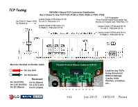
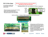
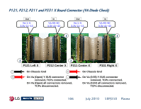
TCP 3.3V B+ Check For Connectors P162 on the Control board, see Control board section. Warning: DO NOT attempt to run the set with the Heat Sink over the TCPs removed. Checking IC231 for 3.3V, use center pin or Case of component. With all connectors connected, place the Red Lead On 3.3V Diode Check (1.9V) Black Lead On 3.3V Diode Check (0.6V) This also test IC201 on the Center Board IC231 Gnd 3.29V 4.94V 3.3V for TCPs IC53 on Control Board 3.3V in on Pins 1 ~ 5 only on P232 connector from the Control board Center X Board P232 103 3.3V All Connectors to All TCPs look very similar for the 3.3V test point. The trace at pins 32 and 33 of each connector. There is a small feed trough and a Cap, you can use for Test Points. Example here from P204. You can only check for continuity back to IC231, you can not run the set with heat sink removed. July 2010 50PJ350 Plasma
-
 1
1 -
2
-
3
-
4
-
5
-
6
-
7
-
8
-
9
-
10
-
11
-
12
-
13
-
14
-
15
-
16
-
17
-
18
-
19
-
20
-
21
-
22
-
23
-
24
-
25
-
26
-
27
-
28
-
29
-
30
-
31
-
32
-
33
-
34
-
35
-
36
-
37
-
38
-
39
-
40
-
41
-
42
-
43
-
44
-
45
-
46
-
47
-
48
-
49
-
50
-
51
-
52
-
53
-
54
-
55
-
56
-
57
-
58
-
59
-
60
-
61
-
62
-
63
-
64
-
65
-
66
-
67
-
68
-
69
-
70
-
71
-
72
-
73
-
74
-
75
-
76
-
77
-
78
-
79
-
80
-
81
-
82
-
83
-
84
-
85
-
86
-
87
-
88
-
89
-
90
-
91
-
92
-
93
-
94
-
95
-
96
-
97
-
 98
98 -
 99
99 -
 100
100 -
 101
101 -
 102
102 -
 103
103 -
 104
104 -
 105
105 -
 106
106 -
 107
107 -
 108
108 -
109
-
110
-
111
-
112
-
113
-
114
-
115
-
116
-
117
-
118
-
119
-
120
-
121
-
122
-
123
-
124
-
125
-
126
-
127
-
128
-
129
-
130
-
131
-
132
-
133
 |
 |
