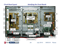
LG 50PJ340 Training Manual - Page 22
Disassembly Procedure for Circuit Board Removal - stand for 50pj350
 |
View all LG 50PJ340 manuals
Add to My Manuals
Save this manual to your list of manuals |
Page 22 highlights
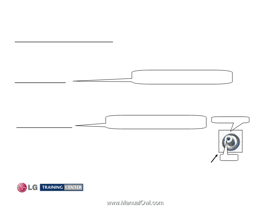
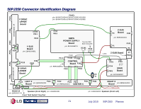
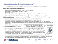
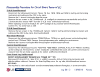
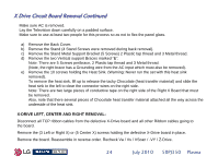
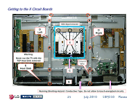
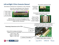
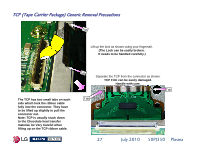
Disassembly Procedure for Circuit Board Removal Note: 1) Remember to be cautious of ESD as some semiconductors are CMOS and prone to static failure. Switch Mode Power Supply Board Removal Disconnect the following connectors: P812, P813 and SC101. Remove the 9 screws holding the SMPS in place. Remove the board. When replacing, be sure to readjust the Va/Vs voltages in accordance with the Panel Label. Also, re-confirm VSC, -Vy and Z-Bias as well. Note: The Y-SUS does not come with the Y-SUS Board Removal connector to the Lower Y-Drive Disconnect the following connectors: P210, P211, P212 and Ribbon Cable P110. To remove P110, lift up on the locking mechanism and pull the ribbon cable out. Remove the 16 screws holding the Y-SUS in place. Do not run the set with P117 or P118 removed. Remove the Y-SUS board. When replacing, be sure to readjust the Va/Vs voltages in accordance with the Panel Label. Confirm VSC, -Vy and Z-bias as well. Note: The Y-SUS does not come with the Board Standoff Y-Drive Boards Removal connectors between the Y-SUS and Y-Drive Disconnect the following Flexible Ribbon Connectors P101~P103 and/or P201~P203: Disconnect P212 by pulling the ribbon cable upward. Remove P204 or P110 by lifting up on the locking mechanism and pull the ribbon cable out. Do not run the set with these connectors removed. Remove the 3 screws holding either of the Y-Drive boards in place. Lift up slightly, the slide to the left. Remove the Y-Drive Board. Collar Note: Y-SUS, Z-SUS and Y-Drive boards are mounted on board stand-offs that have a small collar. The board must be lifted slightly to clear these collars. Behind each board are "Chocolate" (dense rubber like material) that act as shock absorbers. They may make the board stick when removing. 22 July 2010 50PJ350 Plasma
-
 1
1 -
2
-
3
-
4
-
5
-
6
-
7
-
8
-
9
-
10
-
11
-
12
-
13
-
14
-
15
-
16
-
 17
17 -
 18
18 -
 19
19 -
 20
20 -
 21
21 -
 22
22 -
 23
23 -
 24
24 -
 25
25 -
 26
26 -
 27
27 -
28
-
29
-
30
-
31
-
32
-
33
-
34
-
35
-
36
-
37
-
38
-
39
-
40
-
41
-
42
-
43
-
44
-
45
-
46
-
47
-
48
-
49
-
50
-
51
-
52
-
53
-
54
-
55
-
56
-
57
-
58
-
59
-
60
-
61
-
62
-
63
-
64
-
65
-
66
-
67
-
68
-
69
-
70
-
71
-
72
-
73
-
74
-
75
-
76
-
77
-
78
-
79
-
80
-
81
-
82
-
83
-
84
-
85
-
86
-
87
-
88
-
89
-
90
-
91
-
92
-
93
-
94
-
95
-
96
-
97
-
98
-
99
-
100
-
101
-
102
-
103
-
104
-
105
-
106
-
107
-
108
-
109
-
110
-
111
-
112
-
113
-
114
-
115
-
116
-
117
-
118
-
119
-
120
-
121
-
122
-
123
-
124
-
125
-
126
-
127
-
128
-
129
-
130
-
131
-
132
-
133
 |
 |