LG 50PJ340 Training Manual - Page 41
Power Supply Static Test (Forcing on the SMPS in stages
 |
View all LG 50PJ340 manuals
Add to My Manuals
Save this manual to your list of manuals |
Page 41 highlights
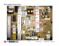
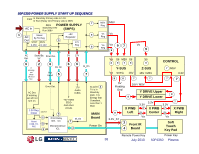
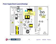
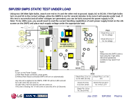
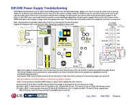
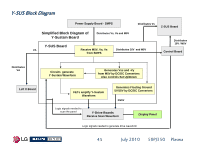
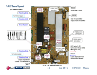
50PJ350 Power Supply Troubleshooting With P813 disconnected from the Main board (P301) attach two 100 Watt light bulbs, attach one end to Vs and the other end to ground. Apply AC to SC101. If the light bulbs turn on and VS is the correct voltage, allow the SMPS to run for several minutes to be sure it will operate under load. If this test is successful and all other voltages are generated, you can be fairly assured the power supply is OK. Note: To be 100% sure, you would need to read the current handling capabilities of each power supply listed on the silk screen on the SMPS and place each supply voltage under the appropriate load. Then follow the instructions below to completely test turn on sequence. Note: Placing the two 100 Watt light bulbs from Vs to Ground will assure the power supply will regulate with a load and no other Abnormal conditions may result. 100W Pins 1 or 2 VS P812 VA VS Test Points T901 VR901 VS Adj F801 4A 250V 100W Gnd Pins 4 or 5 or 8 T902 POWER SUPPLY p/n: EAY60968701 ZD302 D609 ZD401 VR502 VA Adj L601 F302 2.5A 250V T301 F101 10A 250V Use Main Board Side Pin 1 P301 (Front Right) 17V 2 1 17V Gnd 4 3 Gnd +5V 6 5 +5V Error Det 8 7 +5V Gnd 10 9 Gnd Gnd 12 11 Gnd B STBY 5V 14 13 STBY 5V AC Det 16 15 A RL ON 18 17 M_On Auto Gnd L602 P813 C SC101 When the supply is operational in its normal state the Auto Ground line at Pin 18 of P813 is held at ground by the Main Board. This Power Supply can be powered on sequentially to test the Controller Chip IC701 operational capabilities and for troubleshooting purposes. Disconnect P301 from the Main board and use the holes in that end of the connector to insert the jumper and resistors. Warning: Remove AC before adding or removing any plug or resistor. Note: Leave previous installed 100Ω resistor in place when adding the next resistor. (A) Ground the Auto Gnd Line (Pin 18) will allow the supply to be powered up one section at a time. (B) Add a 100Ω ¼ watt resistor from 5V Standby to RL_ON and the AC Det, 17V and 5V Lines on P813 will become active. (C) Add a 100Ω ¼ watt resistor from any 5V line to M_ON (Monitor_On) to make the M5V, VS and VA lines operational. P812 (VS pins 1 and 2) (VA pins 6 and 7) and (M5V pins 9 and 10). 100Ω 100Ω 41 July 2010 50PJ350 Plasma
-
 1
1 -
2
-
3
-
4
-
5
-
6
-
7
-
8
-
9
-
10
-
11
-
12
-
13
-
14
-
15
-
16
-
17
-
18
-
19
-
20
-
21
-
22
-
23
-
24
-
25
-
26
-
27
-
28
-
29
-
30
-
31
-
32
-
33
-
34
-
35
-
 36
36 -
 37
37 -
 38
38 -
 39
39 -
 40
40 -
 41
41 -
 42
42 -
 43
43 -
 44
44 -
 45
45 -
 46
46 -
47
-
48
-
49
-
50
-
51
-
52
-
53
-
54
-
55
-
56
-
57
-
58
-
59
-
60
-
61
-
62
-
63
-
64
-
65
-
66
-
67
-
68
-
69
-
70
-
71
-
72
-
73
-
74
-
75
-
76
-
77
-
78
-
79
-
80
-
81
-
82
-
83
-
84
-
85
-
86
-
87
-
88
-
89
-
90
-
91
-
92
-
93
-
94
-
95
-
96
-
97
-
98
-
99
-
100
-
101
-
102
-
103
-
104
-
105
-
106
-
107
-
108
-
109
-
110
-
111
-
112
-
113
-
114
-
115
-
116
-
117
-
118
-
119
-
120
-
121
-
122
-
123
-
124
-
125
-
126
-
127
-
128
-
129
-
130
-
131
-
132
-
133
 |
 |
