LG 50PJ340 Training Manual - Page 66
Y-Drive Board Layout
 |
View all LG 50PJ340 manuals
Add to My Manuals
Save this manual to your list of manuals |
Page 66 highlights
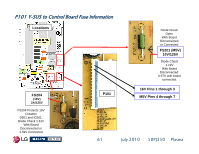
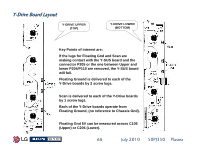
Y-Drive Board Layout Y-DRIVE UPPER (TOP) Y-DRIVE LOWER (BOTTOM) Key Points of interest are; If the lugs for Floating Gnd and Scan are making contact with the Y-SUS board and the connector P205 or the one between Upper and lower P204/P110 are removed, the Y-SUS board will fail. Floating Ground is delivered to each of the Y-Drive boards by 2 screw lugs. Scan is delivered to each of the Y-Drive boards by 1 screw lugs. Each of the Y-Drive boards operate from Floating Ground, (no reference to Chassis Gnd). Floating Gnd 5V can be measured across C105 (Upper) or C205 (Lower). 66 July 2010 50PJ350 Plasma
-
 1
1 -
2
-
3
-
4
-
5
-
6
-
7
-
8
-
9
-
10
-
11
-
12
-
13
-
14
-
15
-
16
-
17
-
18
-
19
-
20
-
21
-
22
-
23
-
24
-
25
-
26
-
27
-
28
-
29
-
30
-
31
-
32
-
33
-
34
-
35
-
36
-
37
-
38
-
39
-
40
-
41
-
42
-
43
-
44
-
45
-
46
-
47
-
48
-
49
-
50
-
51
-
52
-
53
-
54
-
55
-
56
-
57
-
58
-
59
-
60
-
 61
61 -
 62
62 -
 63
63 -
 64
64 -
 65
65 -
 66
66 -
 67
67 -
 68
68 -
 69
69 -
 70
70 -
 71
71 -
72
-
73
-
74
-
75
-
76
-
77
-
78
-
79
-
80
-
81
-
82
-
83
-
84
-
85
-
86
-
87
-
88
-
89
-
90
-
91
-
92
-
93
-
94
-
95
-
96
-
97
-
98
-
99
-
100
-
101
-
102
-
103
-
104
-
105
-
106
-
107
-
108
-
109
-
110
-
111
-
112
-
113
-
114
-
115
-
116
-
117
-
118
-
119
-
120
-
121
-
122
-
123
-
124
-
125
-
126
-
127
-
128
-
129
-
130
-
131
-
132
-
133
 |
 |

66
July 2010
50PJ350
Plasma
Key Points of interest are;
If the lugs for Floating Gnd and Scan are
making contact with the Y-SUS board and the
connector P205 or the one between Upper and
lower P204/P110 are removed, the Y-SUS board
will fail.
Floating Ground is delivered to each of the
Y-Drive boards by 2 screw lugs.
Scan is delivered to each of the Y-Drive boards
by 1 screw lugs.
Each of the Y-Drive boards operate from
Floating Ground, (no reference to Chassis Gnd).
Floating Gnd 5V can be measured across C105
(Upper) or C205 (Lower).
Y
-
Drive Board Layout
Drive Board Layout
Y-DRIVE UPPER
(TOP)
Y-DRIVE LOWER
(BOTTOM)