LG 50PJ340 Training Manual - Page 90
Control Board Connector P111 to Y-SUS P101 Voltages and Diode Mode Checks
 |
View all LG 50PJ340 manuals
Add to My Manuals
Save this manual to your list of manuals |
Page 90 highlights
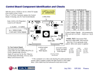
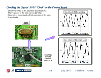
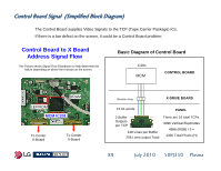
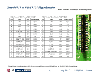
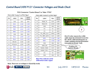
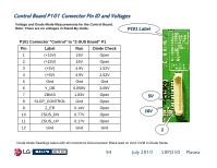
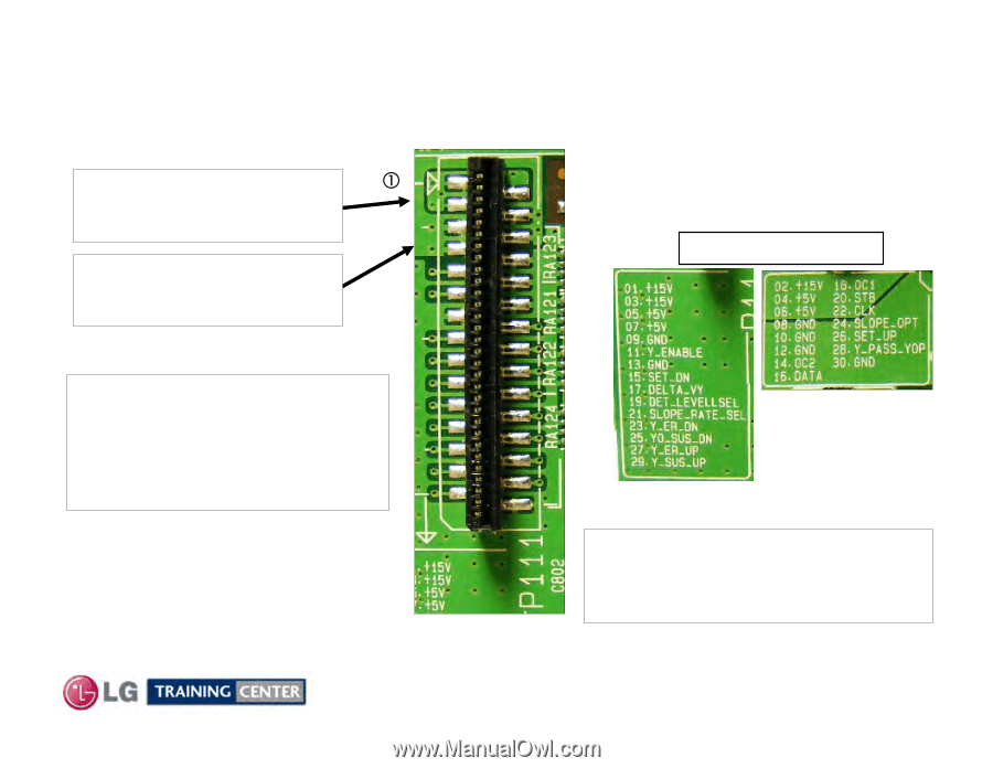
Control Board Connector P111 to Y-SUS P101 Voltages and Diode Mode Checks These pins are very close together. Use Caution when taking Voltage measurements. Pins 1 through 3 Receive 16V from the Y-SUS. Protected on Y-SUS by FS204 Pins 4 through 7 Receive M5V from the Y-SUS. Protected on Y-SUS by FS202 Pin c P111 Label Silk Screen All the rest are delivering Y-SUS Waveform development and Y-Drive logic signals to the Y-SUS Board (Y-Drive logic signals are simply routed right through the Y-SUS to the Y-Drive boards). Note: The +16V is not used by the Control board, it is routed to the Z-SUS leaving on P101 Pins 1~2. The M5V also leaves on P101 Pins 3~4. 90 July 2010 50PJ350 Plasma
-
 1
1 -
2
-
3
-
4
-
5
-
6
-
7
-
8
-
9
-
10
-
11
-
12
-
13
-
14
-
15
-
16
-
17
-
18
-
19
-
20
-
21
-
22
-
23
-
24
-
25
-
26
-
27
-
28
-
29
-
30
-
31
-
32
-
33
-
34
-
35
-
36
-
37
-
38
-
39
-
40
-
41
-
42
-
43
-
44
-
45
-
46
-
47
-
48
-
49
-
50
-
51
-
52
-
53
-
54
-
55
-
56
-
57
-
58
-
59
-
60
-
61
-
62
-
63
-
64
-
65
-
66
-
67
-
68
-
69
-
70
-
71
-
72
-
73
-
74
-
75
-
76
-
77
-
78
-
79
-
80
-
81
-
82
-
83
-
84
-
 85
85 -
 86
86 -
 87
87 -
 88
88 -
 89
89 -
 90
90 -
 91
91 -
 92
92 -
 93
93 -
 94
94 -
 95
95 -
96
-
97
-
98
-
99
-
100
-
101
-
102
-
103
-
104
-
105
-
106
-
107
-
108
-
109
-
110
-
111
-
112
-
113
-
114
-
115
-
116
-
117
-
118
-
119
-
120
-
121
-
122
-
123
-
124
-
125
-
126
-
127
-
128
-
129
-
130
-
131
-
132
-
133
 |
 |
90
July 2010
50PJ350
Plasma
Control
Board Connector P111 to Y
Control
Board Connector P111 to Y
-
SUS P101 Voltages and Diode Mode Checks
SUS P101 Voltages and Diode Mode Checks
These pins are very close together. Use Caution when taking Voltage measurements.
All the rest are delivering
Y-SUS Waveform development and
Y-Drive logic signals to the Y-SUS
Board (Y-Drive logic signals are simply
routed right through the Y-SUS to the
Y-Drive boards).
Pin
P111 Label Silk Screen
Note: The +16V is not used by the Control
board, it is routed to the Z-SUS leaving on
P101 Pins 1~2.
The M5V also leaves on P101 Pins 3~4.
Pins 1 through 3
Receive 16V from the Y-SUS.
Protected on Y-SUS by FS204
Pins 4 through 7
Receive M5V from the Y-SUS.
Protected on Y-SUS by FS202