LG 50PJ340 Training Manual - Page 92
Control Board LVDS P121 Signals
 |
View all LG 50PJ340 manuals
Add to My Manuals
Save this manual to your list of manuals |
Page 92 highlights
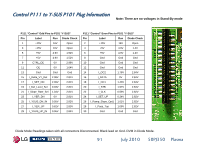
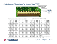
Control Board LVDS P121 Signals LVDS Cable P121 on Control board shown. Press two outside tabs inward to release. P121 LVDS Video Signals from the Main Board to the Control Board are referred to as Low Voltage Differential Signals or LVDS. The video is delivered in 12 bit LVDS format. Their presence can be confirmed with the Oscilloscope by monitoring the LVDS signals with SMPTE Color Bar input. Loss of these Signals would confirm the failure is on the Main Board or the LVDS Cable itself. Example of LVDS Video Signal LVDS LVDS Removed Pins are close together. Example of Normal Signals measured at 1V p/p at 10µSec Pins 2~5, 7~8, 11~12, 15~16, 24~25 are LVDS Video Signals. Pins 9~10 and 22~23 are clock signals for the data. 92 July 2010 50PJ350 Plasma
-
 1
1 -
2
-
3
-
4
-
5
-
6
-
7
-
8
-
9
-
10
-
11
-
12
-
13
-
14
-
15
-
16
-
17
-
18
-
19
-
20
-
21
-
22
-
23
-
24
-
25
-
26
-
27
-
28
-
29
-
30
-
31
-
32
-
33
-
34
-
35
-
36
-
37
-
38
-
39
-
40
-
41
-
42
-
43
-
44
-
45
-
46
-
47
-
48
-
49
-
50
-
51
-
52
-
53
-
54
-
55
-
56
-
57
-
58
-
59
-
60
-
61
-
62
-
63
-
64
-
65
-
66
-
67
-
68
-
69
-
70
-
71
-
72
-
73
-
74
-
75
-
76
-
77
-
78
-
79
-
80
-
81
-
82
-
83
-
84
-
85
-
86
-
 87
87 -
 88
88 -
 89
89 -
 90
90 -
 91
91 -
 92
92 -
 93
93 -
 94
94 -
 95
95 -
 96
96 -
 97
97 -
98
-
99
-
100
-
101
-
102
-
103
-
104
-
105
-
106
-
107
-
108
-
109
-
110
-
111
-
112
-
113
-
114
-
115
-
116
-
117
-
118
-
119
-
120
-
121
-
122
-
123
-
124
-
125
-
126
-
127
-
128
-
129
-
130
-
131
-
132
-
133
 |
 |
