LG 50PJ340 Training Manual - Page 37
Power Supply Basic Operation - as monitor
 |
View all LG 50PJ340 manuals
Add to My Manuals
Save this manual to your list of manuals |
Page 37 highlights
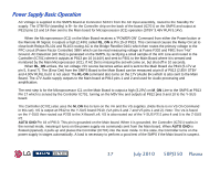
Power Supply Basic Operation AC Voltage is supplied to the SMPS Board at Connector SC101 from the AC Input assembly, routed to the Standby 5V supply. The STBY5V (standby) is B+ for the Controller chip on the back of the board (IC701) on the SMPS and output at P813 pins 13 and 14 then sent to the Main board for Microprocessor (IC1) operation (STBY 3.46V RUN 5.14V). When the Microprocessor (IC1) on the Main Board receives a "POWER ON" Command from either the Power button or the Remote IR Signal, it outputs a high (2.43V) called RL_ON at Pin 15 of P813. This command causes the Relay Circuit to close both Relays RL101 and RL103 routing AC to the Bridge Rectifier D101 which then routes the primary voltage to the PFC circuit (Power Factor Controller) 388V which can be read measuring voltage at Fuses F302 and F801 from "Hot" Ground. AC Detection (AC Det) is generated on the SMPS, by rectifying a small sample of the A/C Line and routed to the Controller (IC701) where it outputs at P813 pin 16 (4.44V) and sent to P301 to the Main Board where it is sensed and monitored by the Main Microprocessor (IC1). If AC Det is missing the set will come on, but shut off in 10 seconds. When RL_ON arrives, the run voltage +5V source becomes active and is sent to the Main Board via P813 (5.17V at pin 5, 6 and 7). The (Error Det) from the SMPS Board to the Main Board can be measured at pin 8 of P813 (2.85V STBY and 4.90V RUN), but it is not used. The RL-ON command also turns on the 17V (Audio B+) which is also sent to the Main Board. The 17V Audio supply outputs to the Main board at P813 pins 1 and 2 and used for Audio processing and amplification. The next step is for the Microprocessor IC1 on the Main Board to output a high (3.29V) on M_ON Line to the SMPS at P813 Pin 17 which is sensed by the Controller IC701, turning on the M5V line and outputs at P812 pins 9 and 10 to the Y-SUS board. The Controller (IC701) also uses the M_ON line to turn on the VA and the VS supplies. (Note there is no VS On Command in this set). VS is output at P812 to the Y-SUS board P210. (VA pins 6 and 7 and VS pins 1 and 2). Note: The Va is fused on the Y-SUS then routed out P203 to the X-Board Left. VS is also routed out of the Y-SUS P211 pins 4 and 5 to the Z-SUS P2. AUTO GND Pin 18 of P813: This pin is grounded on the Main board. When it is grounded, the Controller (IC701) works in the normal mode, meaning it turns on the power supply via commands sent from the Main board. When AUTO GND is floated (opened), it pulls up and places the Controller (IC701) into the Auto mode. In this state, the Controller turns on the power supply in stages automatically. A load is necessary to perform a good test of the SMPS if the Main board is suspect. 37 July 2010 50PJ350 Plasma
-
 1
1 -
2
-
3
-
4
-
5
-
6
-
7
-
8
-
9
-
10
-
11
-
12
-
13
-
14
-
15
-
16
-
17
-
18
-
19
-
20
-
21
-
22
-
23
-
24
-
25
-
26
-
27
-
28
-
29
-
30
-
31
-
 32
32 -
 33
33 -
 34
34 -
 35
35 -
 36
36 -
 37
37 -
 38
38 -
 39
39 -
 40
40 -
 41
41 -
 42
42 -
43
-
44
-
45
-
46
-
47
-
48
-
49
-
50
-
51
-
52
-
53
-
54
-
55
-
56
-
57
-
58
-
59
-
60
-
61
-
62
-
63
-
64
-
65
-
66
-
67
-
68
-
69
-
70
-
71
-
72
-
73
-
74
-
75
-
76
-
77
-
78
-
79
-
80
-
81
-
82
-
83
-
84
-
85
-
86
-
87
-
88
-
89
-
90
-
91
-
92
-
93
-
94
-
95
-
96
-
97
-
98
-
99
-
100
-
101
-
102
-
103
-
104
-
105
-
106
-
107
-
108
-
109
-
110
-
111
-
112
-
113
-
114
-
115
-
116
-
117
-
118
-
119
-
120
-
121
-
122
-
123
-
124
-
125
-
126
-
127
-
128
-
129
-
130
-
131
-
132
-
133
 |
 |