LG 50PJ340 Training Manual - Page 97
X Board (left, Right And Center)
 |
View all LG 50PJ340 manuals
Add to My Manuals
Save this manual to your list of manuals |
Page 97 highlights
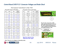
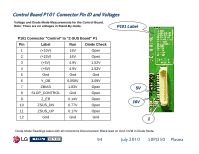
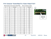
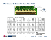
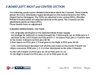
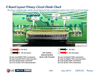
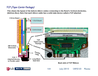
X BOARD (LEFT, RIGHT and CENTER) SECTION The following section gives detailed information about the X boards. These boards deliver the Color information signal developed on the Control board to the TCPs, (Taped Carrier Packages). The TCPs are attached to the vertical FPCs, (Flexible Printed Circuits) which are attached directly to the panel. The X boards are the attachment points for these FPCs. These boards have no adjustment. X-BOARD OPERATIONAL VOLTAGE: • VA: Originally developed on the Switched Mode Power Supply. VA (Voltage for Address) is routed through the Y-SUS board, out on P203 pins 5~7 and then to the Left X board via P122 pins 5~7. Va leaves P121 pins 1~5 and is sent to the Center X-Board via P212 pins 48~50. It then leaves on P211 pins 1~5 and goes to the Right X P331 pins 48~50. • 3.3V: Control board develops 3.3V (IC231) and routes to the Center X board via ribbon connector P232 pins 1~5. It is then distributed to the other X Boards. To the Left X board via P212 pins 41~42 to P121 pins 11~12. To the Right X board via P211 pins 11~12 to P331 pins 41~42. 97 July 2010 50PJ350 Plasma
-
 1
1 -
2
-
3
-
4
-
5
-
6
-
7
-
8
-
9
-
10
-
11
-
12
-
13
-
14
-
15
-
16
-
17
-
18
-
19
-
20
-
21
-
22
-
23
-
24
-
25
-
26
-
27
-
28
-
29
-
30
-
31
-
32
-
33
-
34
-
35
-
36
-
37
-
38
-
39
-
40
-
41
-
42
-
43
-
44
-
45
-
46
-
47
-
48
-
49
-
50
-
51
-
52
-
53
-
54
-
55
-
56
-
57
-
58
-
59
-
60
-
61
-
62
-
63
-
64
-
65
-
66
-
67
-
68
-
69
-
70
-
71
-
72
-
73
-
74
-
75
-
76
-
77
-
78
-
79
-
80
-
81
-
82
-
83
-
84
-
85
-
86
-
87
-
88
-
89
-
90
-
91
-
 92
92 -
 93
93 -
 94
94 -
 95
95 -
 96
96 -
 97
97 -
 98
98 -
 99
99 -
 100
100 -
 101
101 -
 102
102 -
103
-
104
-
105
-
106
-
107
-
108
-
109
-
110
-
111
-
112
-
113
-
114
-
115
-
116
-
117
-
118
-
119
-
120
-
121
-
122
-
123
-
124
-
125
-
126
-
127
-
128
-
129
-
130
-
131
-
132
-
133
 |
 |
