LG 50PJ340 Training Manual - Page 52
Set Up and Set Down Adjustments
 |
View all LG 50PJ340 manuals
Add to My Manuals
Save this manual to your list of manuals |
Page 52 highlights
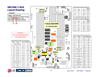
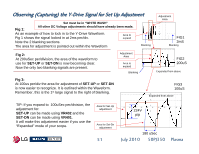
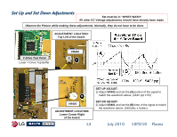
Set Up and Set Down Adjustments Set must be in "WHITE WASH" All other DC Voltage adjustments should have already been made. Observe the Picture while making these adjustments. Normally, they do not have to be done. ADJUSTMENT LOCATION: Top Left of the board. Y-Drive Test Point Lower Y-Drive Top Buffer VR402 A B VR401 ADJUSTMENT LOCATION: Lower Center Right of the board. 52 SET-UP ADJUST: 1) Adjust VR402 and set the (A) portion of the signal to match the waveform above. (224V p/p ± 5V) SET-DN ADJUST: 2) Adjust VR401 and set the (B) time of the signal to match the waveform above. (180uSec ± 5uSec) July 2010 50PJ350 Plasma
-
 1
1 -
2
-
3
-
4
-
5
-
6
-
7
-
8
-
9
-
10
-
11
-
12
-
13
-
14
-
15
-
16
-
17
-
18
-
19
-
20
-
21
-
22
-
23
-
24
-
25
-
26
-
27
-
28
-
29
-
30
-
31
-
32
-
33
-
34
-
35
-
36
-
37
-
38
-
39
-
40
-
41
-
42
-
43
-
44
-
45
-
46
-
 47
47 -
 48
48 -
 49
49 -
 50
50 -
 51
51 -
 52
52 -
 53
53 -
 54
54 -
 55
55 -
 56
56 -
 57
57 -
58
-
59
-
60
-
61
-
62
-
63
-
64
-
65
-
66
-
67
-
68
-
69
-
70
-
71
-
72
-
73
-
74
-
75
-
76
-
77
-
78
-
79
-
80
-
81
-
82
-
83
-
84
-
85
-
86
-
87
-
88
-
89
-
90
-
91
-
92
-
93
-
94
-
95
-
96
-
97
-
98
-
99
-
100
-
101
-
102
-
103
-
104
-
105
-
106
-
107
-
108
-
109
-
110
-
111
-
112
-
113
-
114
-
115
-
116
-
117
-
118
-
119
-
120
-
121
-
122
-
123
-
124
-
125
-
126
-
127
-
128
-
129
-
130
-
131
-
132
-
133
 |
 |

52
July 2010
50PJ350
Plasma
Observe the Picture while making these adjustments. Normally, they do not have to be done.
Set Up and Set Down Adjustments
Set Up and Set Down Adjustments
Y-Drive Test Point
ADJUSTMENT LOCATION:
Lower Center Right
of the board.
SET-UP ADJUST:
1) Adjust
VR402
and set the
(A)
portion of the signal to
match the waveform above. (224V p/p ± 5V)
SET-DN ADJUST:
2) Adjust
VR401
and set the
(B)
time of the signal to match
the waveform above. (180uSec ± 5uSec)
Set must be in “WHITE WASH”
All other DC Voltage adjustments should have already been made.
VR402
VR401
Lower Y-Drive Top Buffer
B
A
ADJUSTMENT LOCATION:
Top Left of the board.